


User’s Manual 4-9
ENHANCING &
CUSTOMIZING
Installing an Interface Expansion Board
Connecting to the Ethernet Port
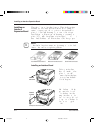
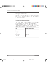
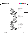
The Ehternet interface board has two connectors, 10BASE-2 and
10BASE-T. The 10BASE-2 connector is for a coaxial cable, bus
connection. The 10BASE-T connector is for a twisted-pair cable, star
connection. Either will do.
Connecting to the Ethernet port involves the following three tasks:
• Check the type of cables your network uses.
• Select the 10BASE-2 or 10BASE-T connector of the interface
board according to the connector type of your cable.
• Connect the interface cable to the printer and a network port.
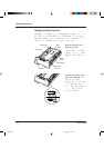
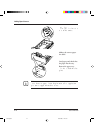
Connecting the Ethernet Interface Cable
To connect to the Ethernet interface port, you need a cable correctly
wired for your network. The cable must also have the proper
connectors. Your dealer or technical support person can supply you
with the proper cable.
For example, C66L-2810-0111 and C66L-1240-0002 (Fujitsu
products) are available for 10BASE-T and 10BASE-2 ports
respectively. Also refer to your network documentation for the type
of connector required by its Ethernet port.
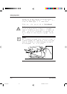
Notice:
Be sure that the printer is turned off before connecting the interface
cable.
Do not touch any connector contacts to avoid possible electrostatic
damage to the printer. For the same reason, do not remove the
protective cover from the 10BASE-2 port which is not in use because
you use the 10BASE-T port.
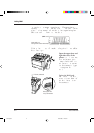
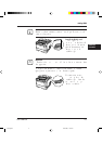
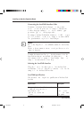
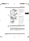
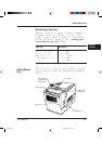
The procedure below applies to the 10BASE-2 port.
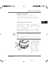
To make the connection, firmly plug the cable connector into the
Ethernet interface port on the back right of the printer. Secure the
connector by turning the connector hood. Plug the other connector
into a network’s Ethernet port. Consult your computer
documentation if you need help.
☞
06 Chapter 4 07.08.1997, 11:41 Uhr9