


100
Chapter 6: Connecting Accessories
General-purpose probing
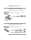
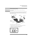
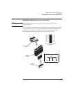
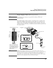
Connecting probe leads to the target. The signal and ground leads
can be connected directly to the target system. This requires installing 0.63
mm (0.025 inch) square pins, or round pins with a diameter between 0.66 and
0.84 mm (0.026 and 0.033 inch) directly on the board. You can also use an IC
test clip with pins with those dimensions.
You can also connect the leads using through-hole grabbers that have small
enough hooks to fit around adjacent IC pins, or by using surface-mount
grabbers designed for fine surface-mount component leads.
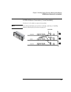
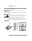
Grounding. Proper grounding will improve the signal quality and is essential
for high speed measurements. Each pod has a pod ground lead, which must be
used. If you use this ground only, signal quality for high speed signals will be
poor.
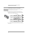
For better results, ground not only the pod, but every third or fourth lead.
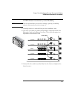
For best results, and when probing signals with rise and fall times of 1 ns or
less, ground each probe lead with no more than a 2-inch ground lead as well as
grounding the pod with the pod ground lead.
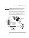
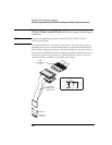
Replacing damaged leads. You can replace damaged leads. Disconnect
individual probe leads by pushing on the latch at the lead base with a ball-
point pen.
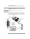
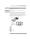
Connecting grabbers to the leads. Connect grabbers to the leads by
slipping the end of the lead over the recessed pin located in the side of the
grabber.