


103
Chapter 6: Connecting Accessories
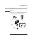
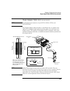
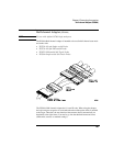
38-pin Low-voltage Probe (E5339A with tip isolation network)
38-pin Low-voltage Probe (E5339A with tip isolation network)
NOTE: For all Agilent logic analyzers except 16517A, 16518A, 16760A, and
16753/54/55/56A.
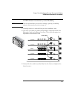
The 38-pin low-voltage probe provides a convenient way to connect
two Agilent Technologies logic analyzer probe cables to a small area of
a target system. The Agilent E5339A probe has isolation networks in
the cable end that connects to the high-density AMP MICTOR
(Matched Impedance ConnecTOR) connector. It is designed to be
compatible with low-amplitude digital signals, down to 250 mV p-p.
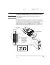
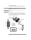
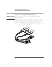
Logic Analyzer
Pod
Probe Cable
(with RC network)
Shroud
Amp "MICTOR 38”
Connector
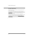
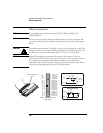
AMP "MICTOR 38"
Connector Pinout
E
v
e
n
P
o
d
+5VDC
GND DC
CLK
D15
D14
D13
D12
D11
D10
D9
D8
D7
D6
D5
D4
D3
D2
D1
D0
1
3
5
7
9
11
13
15
17
19
21
23
25
27
29
31
33
35
37
O
d
d
P
o
d
Do not connect
Do not connect
CLK
D15
D14
D13
D12
D11
D10
D9
D8
D7
D6
D5
D4
D3
D2
D1
D0
2
4
6
8
10
12
14
16
18
20
22
24
26
28
30
32
34
36
38
Equivalent Load
220
ohm
Signal
Ground
Includes lo
g
ic analyzer and MICTOR connector.
18pF3pF
50.5k
ohm
Note:
DO NOT
connect these pins to
a +5V supply in the
target system!
+5V is supplied
from the logic analyzer
to provide power for
analysis probes and
demo boards.