


Introduction
Probe Overview
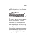
10
Status LEDs
Your probe has status LEDs for the base hardware configuration (the 10Base-T/
100Base-TX telemetry interface), for the OC-3 ATM interface, and for the
optional Token-Ring telemetry interface.
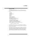
The following sections cover the possible status LEDs on your OC-3 ATMProbe:
“10Base-T/100Base-TX Telemetry Interface Status LEDs” below
“Token-Ring Telemetry Interface Status LEDs” on page 12
“OC-3 ATM Interface Status LEDs” on page 13
10Base-T/100Base-TX Telemetry Interface Status LEDs
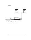
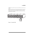
The status LEDs for the 10Base-T/100Base-TX telemetry interface are visible on
the front and back of the probe. Figure 1-3 on page 11 shows the LEDs on the
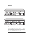
front of the probe and Figure 1-4 on page 12 shows the LEDs on the back of the
probe.
The ~ Line On, Activity, and Fault LEDs are on the front of the probe.
On the back of the probe, there are LEDs associated specifically with each
interface and a Power LED. The 10Base-T/100Base-TX telemetry interface has
LEDs for Activity, Link and Collision.
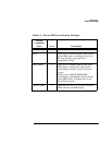
Refer to the following list for information on how these LEDs work:
~ Line On
or
Power
. This green LED is turned on when the probe is receiving
power.
Activity
. This green LED is turned on when data is being received from the
Ethernet telemetry network or transmitted by the probe. When flashing, the
frequency shows the amount of traffic. During periods of steady traffic, it may
appear to stay on solid.
Link.
This green LED is turned on when the probe is attached to a 10Base-T/
100Base-TX network.