


Introduction
Probe Overview
13
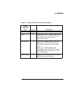
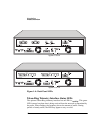
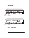
OC-3 ATM Interface Status LEDs
The Agilent J3919A ATM interface has LEDs for Activity and Cell Sync
functions. The Agilent J3972A ATM interface additionally has a Fault LED. Refer
to the following list for information on how these LEDs work:
Activity
. This green LED is turned on when valid cells are received by the OC-3
ATM interface from the network. When flashing, the frequency shows the amount
of traffic. During periods of steady traffic, the LED may appear to stay on solid.
Cell Sync
. This yellow LED is turned on when the OC-3 ATM interface detects a
loss of cell synchronization.
The following LED is on the Agilent J3972A probe only:
Fault
. This yellow LED is turned on when the processor on the Agilent J3972A
probe is not running. The Fault LED can turn on during the power-on self-test, but
should be off when the probe is running.
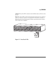
CONFIG Button
The CONFIG button is used to configure the probe from a terminal or to restart
the probe. The CONFIG button is recessed and located on the back of the probe
near the RS-232C connector. You will need to use a narrow, pointed object (like a
pen) to press the CONFIG button.
To configure the probe using a local terminal (or PC emulating a terminal),
connect a terminal to the probe using a null modem cable and push the CONFIG
button to display the probe’s Main Menu. This operation is described in Chapter 2
“Local Terminal Configuration”.
You can restart the probe (with a warm start or cold start) using the CONFIG
button. These functions are described in Chapter 5 “Probe Operation”.