


AT-9000 Switch Command Line User’s Guide
733
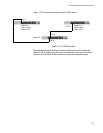
Figure 137 provides an example of how GVRP works.
Figure 137. GVRP Example
The example consists of three switches. Switches #1 and #3 have the
Sales VLAN, but switch #2 does not. Consequently, the end nodes of the
two parts of the Sales VLANs cannot communicate with each other.
Port 1
Port 2
Port 4
Port 3
Switch #3
Static VLAN
Sales VID 11
Switch #1
Static VLAN
Sales VID 11
Switch #2