


Appendix A: Technical Specifications
106
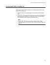
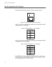
RJ-45 Twisted Pair Port Pinouts
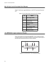
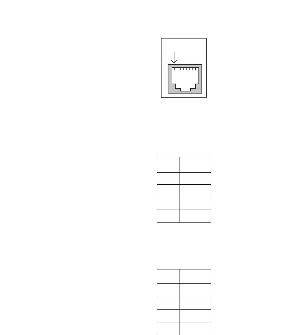
Figure 49 illustrates the pin layout of an RJ-45 connector and port.
Figure 49. RJ-45 Connector and Port Pin Layout
Table 13 lists the pin signal definitions when a port is operating in the MDI
configuration at 10 or 100 Mbps.
Table 14 lists the pin signal definitions when a port is operating in the MDI-
X configuration at 10 or 100 Mbps.
The MDI/MDI-X setting is established automatically when a port is set to
Auto-Negotiation. If a port’s speed and duplex are set manually, the MDI/
MDI-X setting defaults to the MDI-X setting.
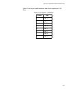
Table 13. MDI Pin Signals - 10 or 100 Mbps
Pin Signal
1TX+
2TX-
3RX+
6RX-
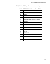
Table 14. MDI-X Pin Signals - 10 or 100 Mbps
Pin Signal
1RX+
2RX-
3TX+
6TX-
Pin 1