


x600 Series Layer 3 Gigabit Ethernet Switches Installation Guide
33
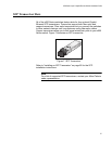
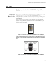
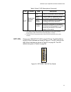
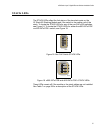
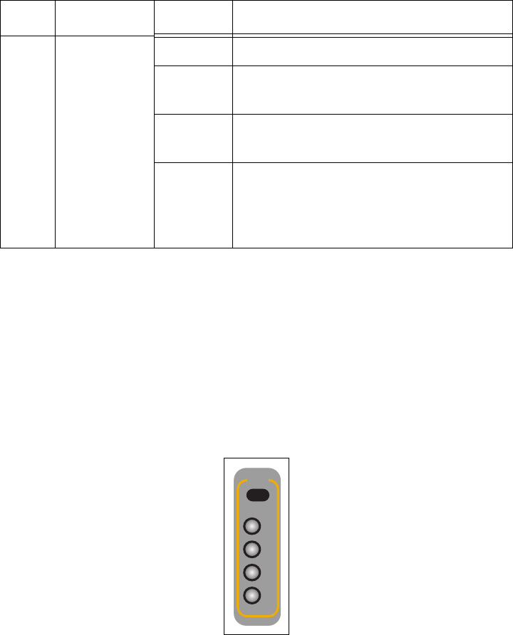
SFP LEDs There is one LINK/ACTIVITY LED for each SFP slot. The SFP LEDs for
the x600 24 port switches are shown in Figure 14. The SFP LEDs for the
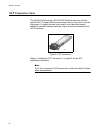
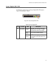
x600 48 port switches are shown in Figure 15 on page 34. The LED
definition are given in Table 4 on page 34
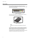
Figure 14. SFP LEDs - x600-24 Port Switch
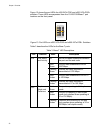
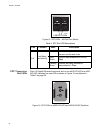
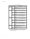
PoE
2
Power over
Ethernet
Status
Off There is no powered device detected.
Solid
Green
The end-node is a powered device
and the port is providing power to it.
Solid
Amber
The port is experiencing a problem
providing PoE to the end-node.
Flashing
Amber
The port is connected to a powered
device but providing power to it would
exceed the maximum PoE power
budget of the switch.
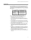
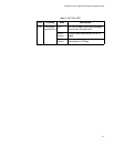
1. The Duplex Mode and Collisions LED is present on all the x600 switches
except for the x600-24Ts-POE and x600-24Ts-POE+ switches.
2. The PoE LED is only present on the x600-24Ts-POE and x600-24Ts-POE+
switches.
Table 3. Base-T LED Descriptions (Continued)
LED Function State Description
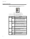
161
21
22
23
24
SFP
L/A