


Chapter 1: Overview
46
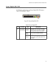
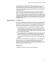
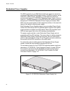
Redundant Power Supplies
The RPS connector on an x600 Series switch rear panel can connect to
an optional Redundant Power Supply module. The RPS connector on the
x600-24Ts, x600-24Ts/XP, x600-48Ts, or x600-48Ts/XP switch can
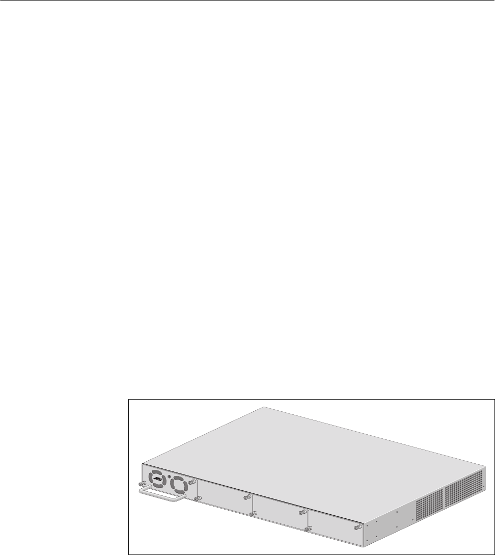
connect to the optional AT-RPS3204 Redundant Power Supply, shown in
Figure 21. The RPS connector on the x600-24Ts-POE switch connects to
the optional AT-RPS3104 Redundant Power Supply (not shown). Both
RPS units can provide power to their respective switches in the event of a
failure of the switch’s internal power supply.
Both Redundant Power Supplies feature one pre-installed Power Supply
module and three empty slots for additional power supplies. Each power
supply module can support one x600 switch. When fully populated, each
RPS unit can support up to four x600 switches simultaneously.
The power supply modules in each Redundant Power Supply are hot
swappable with the x600 switches. This means that it is safe to connect a
Redundant Power Supply module with its power ON to an x600 switch
(which is also powered on) using a 21-pin D-combo connector cable from
the module into the RPS connector on the x600 switch.
For information about installing each of the Redundant Power Supply
models, consult the documentation shipped with the unit.
The connector pinouts for the AT-RPS3104 redundant power supply are
described in “AT-RPS3104 17-pin Connector Pinouts” on page 108 and
the connector pinouts for the AT-RPS3204 redundant power supply’s
connector are described in “AT-RPS3204 21-pin D-combo Port and
Connector Pinouts” on page 110.
Figure 21. AT-RPS3204 Redundant Power Supply Unit
AT-PWR3204
PO
W
E
R