


x600 Series Layer 3 Gigabit Ethernet Switches Installation Guide
19
Switch Descriptions
The following sections describe the x600 Series Layer 3 Gigabit Ethernet
Switches.
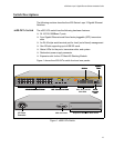
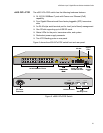
x600-24Ts Switch The x600-24Ts switch has the following hardware features:
24 10/100/1000Base-T ports
Four Gigabit Ethernet small form-factor pluggable (SFP) transceiver
slots
An RJ-45 style serial terminal port for local (out-of-band) management
One SD slot supporting up to 4GB SD cards
Status LEDs for the ports, transceiver slots, and system
Redundant power supply connector
Expansion slot for the AT-StackXG Stacking Module
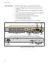
Figure 1 shows the x600-24Ts switch front and rear panels.
Figure 1. x600-24Ts Switch
RPS INPUT
100-240VAC~
1310
AC Power
Connector
System
LEDs
RPS Connector
Expansion Slot with Blank Panel
1 3 5 7 9 11 13 15 17 19 21R 23R
2 4 6 8 10 12 14 16 18 20 22R 24R
x600-24Ts
Layer 3 Gigabit Ethernet Switch
CLASS 1
LASER PRODUCT
D/C
L/A
1000 LINK / ACT
HDX /
COL
FDX
10/100 LINK / ACT
PORT ACTIVITY
L/A
D/C
D/C
L/AL/A
PRES
MSTR
L/A
1
2
SFP
21 22 23 24
1 3 5 7 9 11 13 15 17 19 21R23R
2 4 6 8 10 12 14 16 18 20 22R24R
FAU LT
RPS
MASTER
PWR
STATUS
21
22
23
24
SFP
L/A
BUSY
READY
FAULT
SD
RESET
CONSOLE
STACK
1329
SFP Transceiver Slots RJ-4510/100/1000Base-T Ports Port, SFP, and SD
Slot LEDs
10/100/1000Base-T Ports
SD Slot
Console
Port
System
LEDs
SFP Transceiver Slots
RJ-4510/100/1000Base-T Ports
SD Slot
Console
Port