


Chapter 2: Virtual Chassis Stacking
54
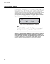
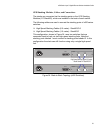
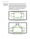
Ring Configuration
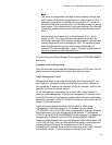
A virtual stack using x600 switches can comprise up to 4 stack members
connected in a ring topology. Figure 25 shows a ring comprising 3 stacked
x600 series switches. Because an alternate path is provided between the
stack members, this topology offers a very resilient configuration
Figure 25. VCS Ring Topology Using x600 Switches
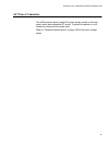
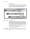
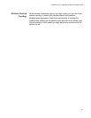
Resiliency Link Stack Resiliency Link
The purpose of the resiliency link is to provide the stack members with
status information that enables them to detect whether the stack master is
still operational after it has suffered either a power-down or software lock-
up. This enables the other stack members to either operate in the fall-back
mode, or to re-elect a new stack master. The state change table,Table 10,
“State Change Table” on page 55 shows how the stack members respond
to various problems occurring on the master node.
A resiliency link operates using a resiliency link VLAN to which resiliency
link switch ports can become members.
VCStack
Recovery States
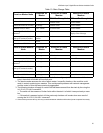
The following state-change-table shows stack member failure conditions
and recovery actions in situations where the resiliency link is present or
absent.
RPS INPUT
100-240VAC~
AT-StackXG
AT-StackXG
STACK PORT 2
RPS INPUT
100-240VAC~
RPS INPUT
100-240VAC~
AT-StackXG
AT-StackXG
STACK PORT 2
STACK PORT 1
STACK PORT 1
AT-StackXG
STACK PORT 1 STACK PORT 2
High Speed Stacking Cables
Model Number AT-StackXG/0.5
(0.5 metres)
High Speed Stacking Cables
Model Number AT-StackXG/0.5
(0.5 meters) as supplied or
Model Number AT-StackXG/1
(1.0 meter)
High Speed Stacking Cables
Model Number AT-StackXG/0.5
(0.5 metres)