


x600 Series Layer 3 Gigabit Ethernet Switches Installation Guide
53
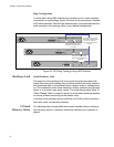
VCS Stacking Modules, Cables, and Connections
The stacks are connected via the stacking ports on the VCS Stacking
Modules (AT-StackXG), which are installed in the back of each switch.
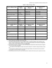
The following cables are used to connect the stacking ports of x600 series
switches:
High Speed Stacking Cables (0.5 meter) - StackXG/0.5
High Speed Stacking Cables (1.0 meter) - StackXG/1
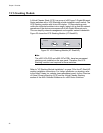
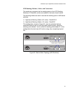
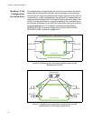
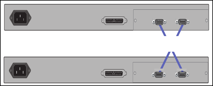
This configuration, shown in Figure 24,
uses two switches that are
connected back to back via two high-speed stacking links. Note that
stacking ports labeled 1 must connect to stacking ports labeled 2. In this
configuration the stack can still function using only a single high speed
link.
Figure 24. Back-to-Back Topology (x600 Switches)
RPS INPUT
100-240VAC~
AT-StackXG
AT-StackXG
RPS INPUT
100-240VAC~
AT-StackXG
AT-StackXG
STACK PORT 1
STACK PORT 2
STACK PORT 1 STACK PORT 2
High Speed Stacking Cables (0.5 meter)
Model Number AT-StackXG/0.5