


Chapter 2: Virtual Chassis Stacking
60
management VLAN ID and IP address, use the SHOW STACK command.
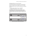
Stack Member Identification
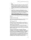
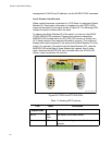
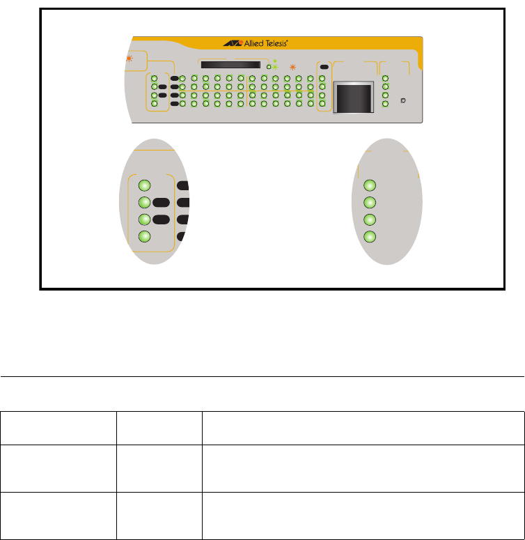
When a switch becomes a member of a VCS Stack it is assigned a Stack
Member-ID. Stack status information is displayed on the STACK LEDs
shown on the switch’s front panel shown in Figure 28. The following LEDs
indicate the switch’s status within the stack.
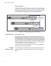
To observe the Stack Member-ID of the switch, you first run the SHOW
STACK INDICATOR command
. Running this command causes the
MASTER LED (located within the STATUS LED column) to initially turn
off. A flash sequence then appears followed by a pause. The number of
flashes within each sequence is the same as the Stack Member-ID of the
switch. For example, if the switch had the Stack Member-ID 4, then the
MASTER LED would flash 4 times followed by a pause, then 4 times
again. Note that the MSTR LED that is located within the STACK LED
column, does not perform this function.
Figure 28. STACK and STATUS LEDs
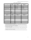
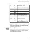
Table 11. Stacking LED Functions
LED State Description
STACK LEDs
MSTR Solid
Green
The switch is the Stack Master.
OFF The switch is acting as a stack back-up
member.
FAULT
RPS
MASTER
PWR
STATUS
x600_VCS_STK_LEDs
x600-24Ts
Layer 3 Gigabit Ethernet Switch
OL
ACT
L/A
D/C
D/C
L/AL/A
STAC K
PRES
MSTR
L/A
1
2
1 3 5791113 15 17 19 21R 23R
2468 10 12 14 16 18 20 22R 24R
FAULT
RPS
MASTER
PWR
STATUS
21
22
23
24
SFP
L/A
BUSY
READY
FAU LT
SD
RESET
CONSOLE
L/A
D/C
D/C
L/AL/A
STACK
PRES
MSTR
L/A
1
2