


Appendix A: Technical Specifications
108
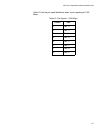
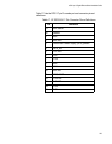
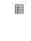
RJ-45 Style Serial Terminal Port Pinouts
Table 16 lists the pin signal definitions on the RJ-45 style serial terminal
port.
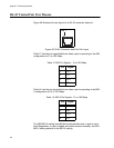
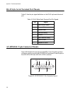
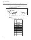
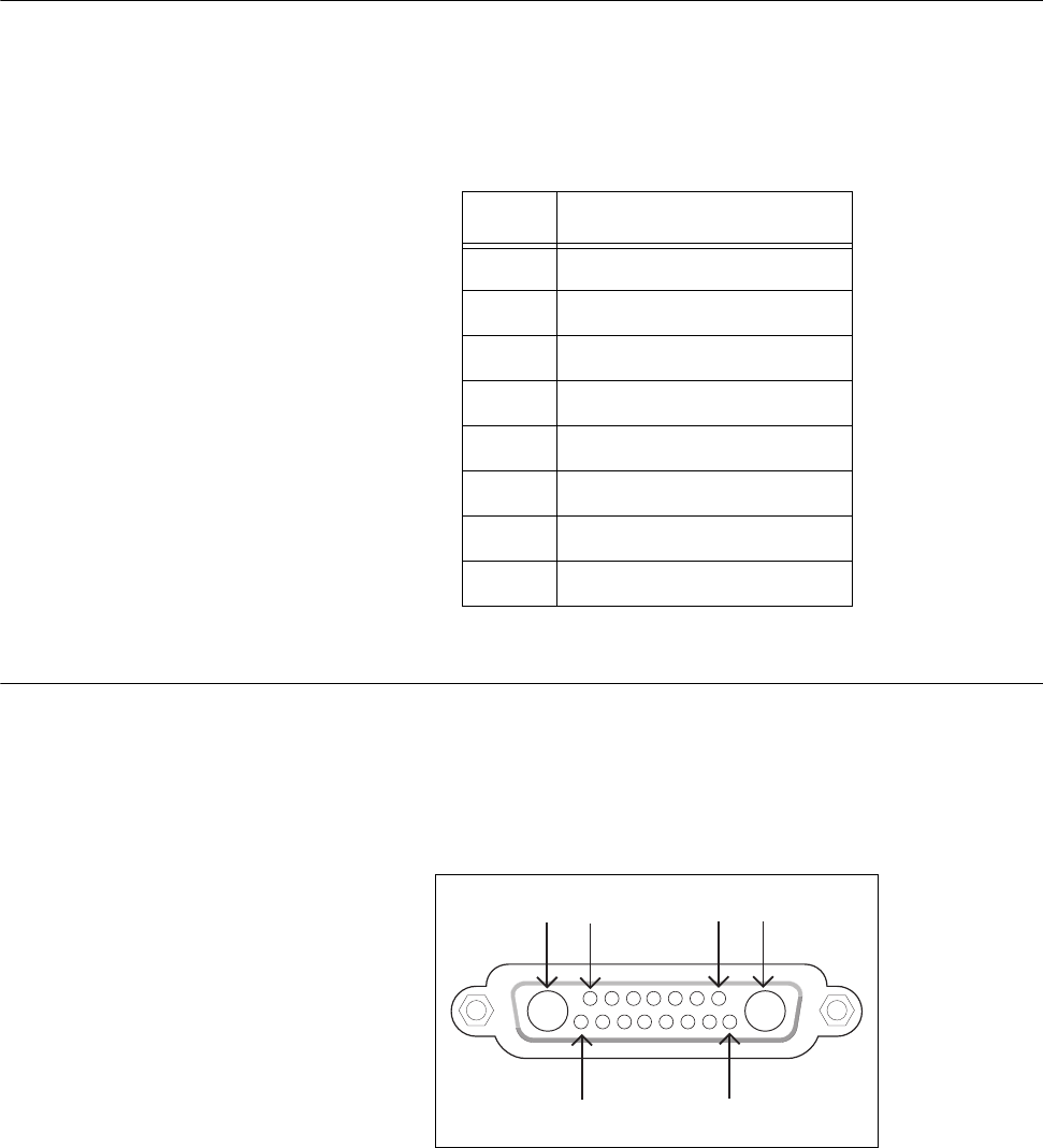
AT-RPS3104 17-pin Connector Pinouts
Figure 50 illustrates the pin layout of the RPS 17-pin D-combo port and
connector used to connect the AT-RPS3104 Redundant Power Supply to
the x600-24Ts-POE and x600-24Ts-POE+ switches.
Figure 50. AT-RPS3104 17-Pin Connector Layout
Table 16. RJ-45 Style Serial Terminal Port Pin Signals
Pin Signal
4 Data Carrier Detect
3 Transmit Data
6 Receive Data
7 Data Set Ready
5 Ground
2 Data Terminal Ready
8 Clear to Send
1 Request to Send
A1A2 17
15 8