


Chapter 2: Virtual Chassis Stacking
56
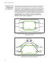
Resiliency Link
Configurations
via Switch Ports
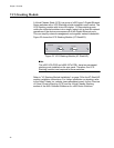
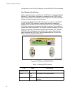
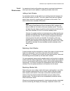
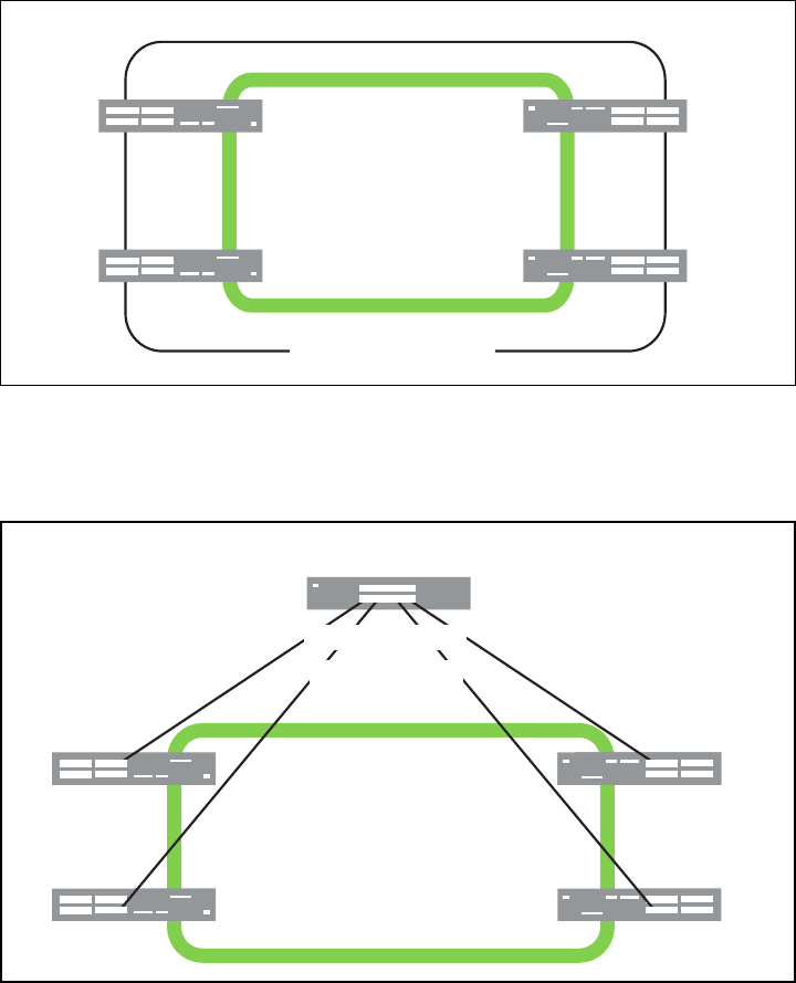
Two resiliency-link configurations that connect to switch ports are shown
below:Figure 26 shows the resiliency link connecting in a ring topology,
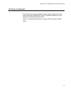
whilst Figure 27 shows the resiliency link connecting to its switch ports via
a network hub. In both configurations, the resiliency link connections are
made using the ResiliencyLink VLAN and attaching the switch ports to the
VLAN. For more information on using the resiliency link commands go to
the Software Reference for the x600 Series Switches which can be found
at www.alliedtelesis.com. The specific commands are the STACK
RESILIENCYLINK command on page 86.27 and the SWITCHPORT
RESILIENCYLINK command on page 86.30.
Figure 26. Resiliency link connecting to switch ports over the
ResiliencyLink VLAN
Figure 27. Resiliency link connecting to switch ports over the
ResiliencyLink VLAN using a network hub
x600-24Ts
x600-24Ts
x600-24Ts
x600-24Ts
Stacking Links
Connecting to Switch PortsStack Resiliency Link -
ResiliencyLink VLAN
x600-24Ts
x600-24Ts
x600-24Ts
Network Hub
x600-24Ts
Stacking Links
Resiliency Links
to Switch Ports