


x600 Layer 3 Gigabit Ethernet Switch Installation Guide
89
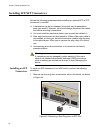
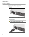
3. Connect the other end of the power cord to an appropriate AC power
outlet. For power specifications for the switch, refer to “Power
Specifications” on page 104.
4. Start a local management session on the unit by performing the next
procedure.
Starting a Local
Management
Session
The following procedure describes how to connect an RJ-45 cable to an
x600 switch. For information about how to log onto the AlliedPlus
TM
Operating System Software, see the AlliedWare Plus
Operating System
Software Reference Guide.
To start a local management session on the unit, perform the following
procedure:
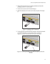
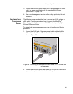
1. Connect the RJ-45 end of the management cable included with the
x600 switch to the Terminal Port on the front panel of the switch, as
shown in Figure 48.
Figure 48. Connecting the Management Cable to the RJ-45 Terminal Port
on the Switch
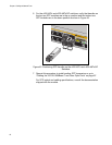
2. Connect the other end of the cable to an RS-232 port on a terminal or
a personal computer with a terminal emulation program.
1320
x600-24Ts/XP
Layer 3 Gigabit Ethernet Switch
9 11 13 15 17 19 21R 23R
10 12 14 16 18 20 22R24R
FAUL
T
RPS
MASTER
PWR
STATUS
21
22
23
24
SFP
L/A
BUSY
READY
FAU LT
SD
RESET
CONSOLE