


x600 Layer 3 Gigabit Ethernet Switch Installation Guide
75
Installing the
AT-StackXG
Module
To install the AT-StackXG module, perform the following procedure:
1. Remove the module from the shipping package.
Note
Store the packaging material in a safe location. You must use the
original shipping material if you need to return the unit to Allied
Telesis.
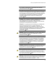
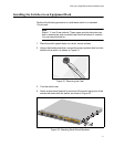
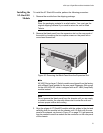
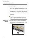
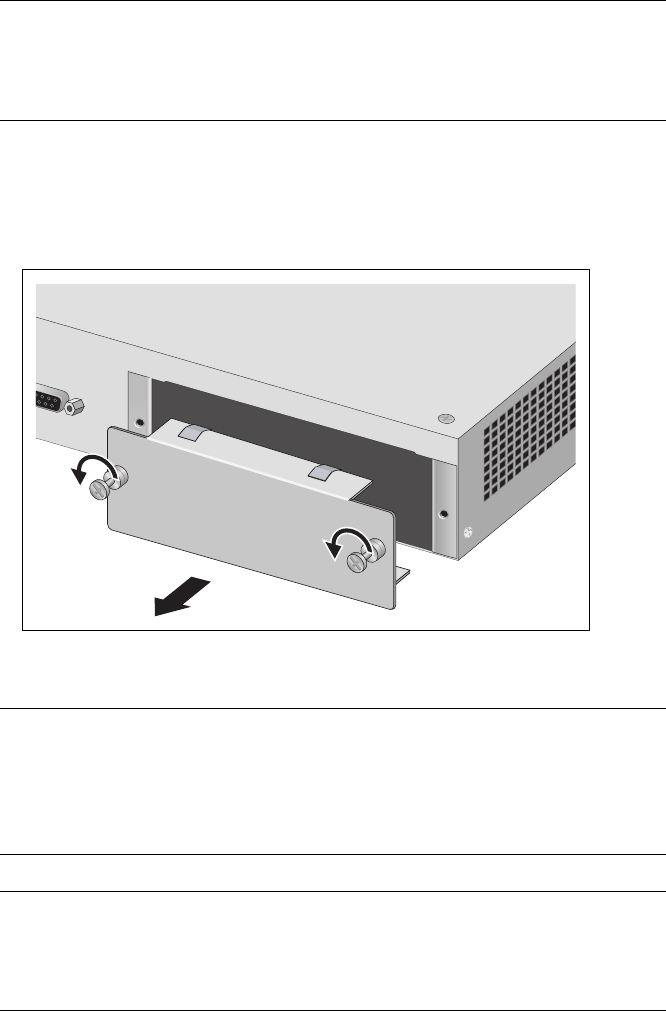
2. Remove the blank panel from the expansion slot on the rear panel of
the switch by loosening the two captive screws on the panel with a
cross-head screwdriver.
Figure 36. Removing the Blank Panel from the Expansion Slot
Note
All X600 Series Layer 3 Switch models are shipped from the factory
with a Blank Panel installed in the rear panel Expansion Slot except
for the x600-48Ts/XP, which is shipped with an AT-LBM (Loop Back)
module instead.
Note
Do not remove the blank panel from the chassis until you are ready
to install a module. An open slot allows dust to enter the unit and
reduces proper airflow and cooling.
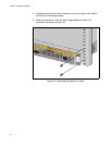
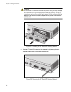
3. Align the edges of AT-StackXG module with the guides in the slot and
carefully slide the module into the chassis until it is flush with the rear
panel of the chassis, as shown in Figure 37 on page 76. Light pressure
may be needed to seat the module on the connector on the rear panel
of the chassis.
1241
AT-LX44CPUCV
R