


x600 Layer 3 Gigabit Ethernet Switch Installation Guide
71
Installing the Switches in an Equipment Rack
Perform the following procedure to install each switch in a standard
19-inch rack:
Note
Steps 1, 2, and 3 are optional. These steps provide instructions on
how to remove the snap-on plastic feet from the bottom of a switch.
You can leave the feet on.
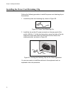
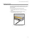
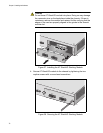
1. Place the switch upside down on a level, secure surface.
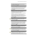
2. Using a flat-head screwdriver, remove the snap-on plastic feet from the
bottom of the switch, as shown in Figure 31.
Figure 31. Removing the Feet
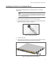
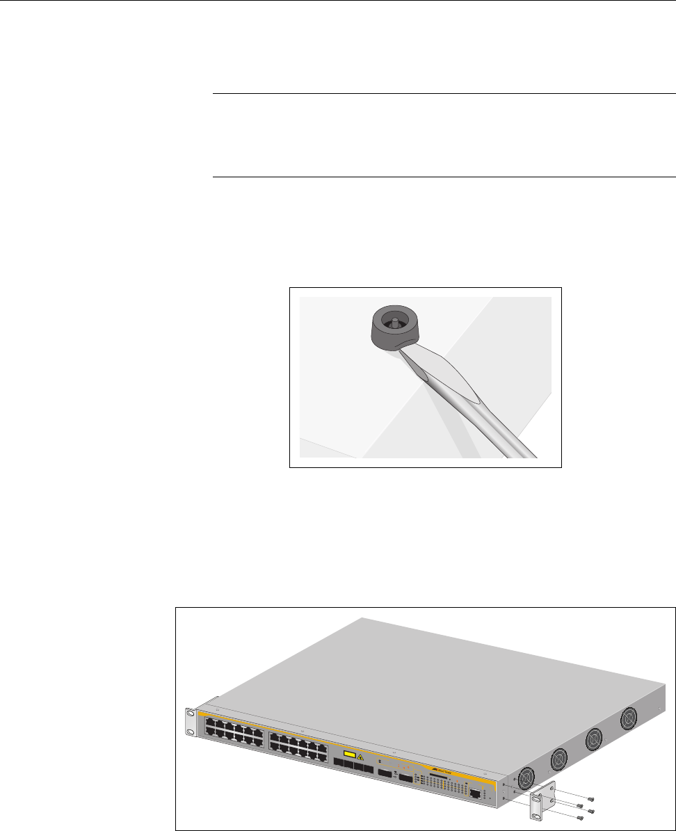
3. Turn the switch over.
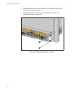
4. Attach a rack-mount bracket to one side of the switch using four of the
screws that come with the switch, as shown in Figure 32.
Figure 32. Attaching Rack-Mount Brackets
1327
135
7
9
11
13 1
517
19 2
1R
23R
246
81012
14
1
6
18 20 2
2R
24R
x600-24Ts/XP
Layer 3 Gigabit Ethenet Switch
C
L
A
S
S
1
L
A
S
E
R
P
R
O
D
U
C
T
D
/
C
L
/
A
1
0
0
0
L
I
N
K
/
ACT
H
D
X
/
C
O
L
F
D
X
1
0
/
1
0
0
L
I
N
K
/
A
C
T
P
ORT
A
C
T
IV
IT
Y
26
25
L
/A
X
F
P
X
F
P
L/A
D/C
D/C
L/A
L/A
S
T
AC
K
P
R
E
S
M
S
T
R
L/A
1
2
S
F
P
2
122
2
3
24
1
35
7
91113
1
51
7
1921R23R
24
68
1
0
1
2
1
4
1
61
8
2022
R
24R
FAU
LT
R
P
S
M
A
S
T
E
R
P
W
R
S
T
ATUS
2
1
2
2
2
3
2
4
S
F
P
L/A
B
U
S
Y
R
E
A
D
Y
FAULT
S
D
R
ES
E
T
C
O
N
S
O
L
E