


Chapter 1: Overview
32
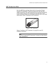
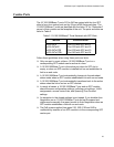
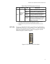
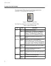
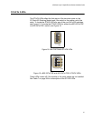
Figure 13 shows the port LEDs for x600-24Ts-POE and x600-24Ts-POE+
switches. These LEDs are separated from the 10/100/1000Base-T port
locations on the front panel.
Figure 13. Port LEDs on x600-24Ts-POE and x600-24Ts-POE+ Switches
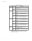
Table 3 describes the LEDs for the Base-T ports.
Table 3. Base-T LED Descriptions
LED Function State Description
L/A Link Status
and Activity
Off No link has been established between
the port and the end node.
Solid
Green
The port has established a link at
1000 Mbps.
Flashing
Green
Packets are being received or
transmitted at 1000 Mbps.
Solid
Amber
The port has established a link at 10
or 100 Mbps.
Flashing
Amber
Packets are being received or
transmitted at 10 or 100 Mbps.
D/C
1
Duplex
Mode and
Collisions
Solid
Green
The port is operating in full-duplex
mode.
Solid
Amber
The port is operating in half-duplex
mode (only applies when operating at
10 or 100 Mbps).
Flashing
Amber
Collisions are occurring on the port
(only applies when operating at 10 or
100 Mbps, half duplex mode).
L/A
L/A
13
24
PoE
PoE