


AMF Commands
AMF Software Reference Supplement for Allied Telesis x-Series Switches
C613-50031-01 REV B AlliedWare Plus
TM
Operating System - Software Version 5.4.3-1.4 and later 81
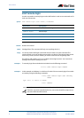
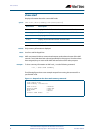
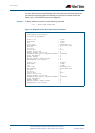
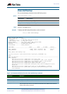
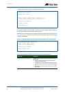
Example 2 To show detailed information on AMF node_1 use the following command:
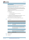
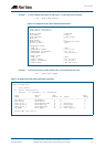
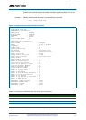
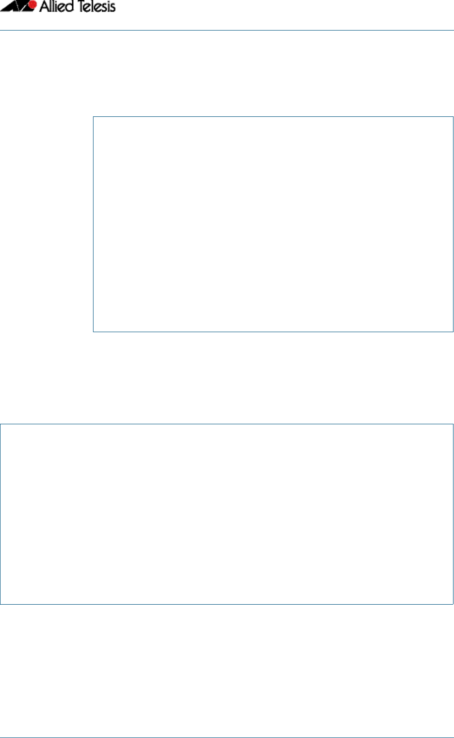
Example 3 To show information specific to AMF nodes use the following command:
node_1
show atmf detail
Figure 1-2: Output from the show atmf detail command
node_1#show atmf detail
ATMF Detail Information
Network Name : ATMF_NET
Node Name : node_1
Node Address : node_1.atmf
Node ID : 1
Node Depth : 0
Domain State : DomainController
Recovery State : None
Management VLAN
VLAN ID : 4092
Management Subnet : 172.31.0.0
Management IP Address : 172.31.0.1
Management Mask : 255.255.128.0
Domain VLAN
VLAN ID : 4091
Domain Subnet : 172.31.128.0
Domain IP Address : 172.31.128.1
Domain Mask : 255.255.128.0
node_1
show atmf nodes
Figure 1-3: Output from the show atmf nodes command
Node Information:
* = Local device
SC = Switch Configuration:
C = Chassis S = Stackable N = Standalone
Node Device AMF Node
Name Type Master SC Parent Depth
--------------------------------------------------------------------------------
Building_1 AT-SBx8112 Y C - 0
* Building_2 x900-12XT/S Y N - 0
Bld1_Floor_1 SwitchBlade x908 N S Building_1 1
Bld1_Floor_2 x600-24Ts/XP N N Building_1 1
Bld2_Floor_1 x610-24Ts-POE+ N N Building_1 1
SW_Team1 x510-28GPX N N Bld1_Floor_2 2
Current AMF node count 8