


2-12
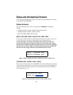
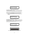
Outlet Status Screens
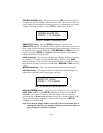
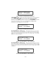
The two screens in Figures 25 and 26 show which of the four outlet banks are turned
on or off. The outlet banks can be turned on or off independently via the RS-232
serial port, which is located on the rear of the unit. In the near future this capability
will also be available via the Web. Refer to Appendix B for directions on how to
setup and use the communication port.
Figure 25. Digital and Video Outlets Status
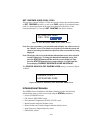
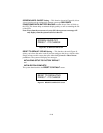
Figure 26. Analog and High Amp Outlets Status
Connecting the Components
Warning: Do not make telephone, cable, Ethernet, antenna, electrical, or ground
system connections during a lightning storm. Failure to comply may
result in personal injury or death.
Due to the unique filtering provided by the S20BLK, APC recommends that you
connect the AV components as shown on the labels on the rear panel of the unit, and
as described in the section Rear Panel Connectors and Circuit Breaker.
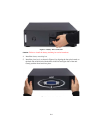
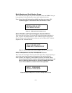
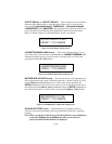
To ensure ground loops are eliminated, and to ensure there is no audible hum in your
speaker system, ground all AV components to the GROUND SYSTEM screw
located on the rear panel, as shown in Figure 27.
Figure 27. Ground System Screw Location
DIGITAL OUTLETS:ON
VIDEO OUTLETS:ON
ANALOG OUTLETS:ON
HI AMP OUTLETS:ON
Ground System
Screw