


ASUS P4R800-V Deluxe motherboard user guide
2-21
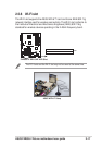
Always connect ribbon cables with the red stripe to Pin 1 on the
connectors. Pin 1 is usually on the side closest to the power connector
on hard drives and CD-ROM drives, but may be on the opposite side
on floppy disk drives.
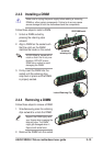
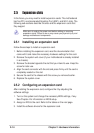
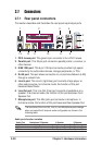
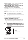
2.7.2 Internal connectors
This section describes and illustrates the internal connectors.
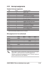
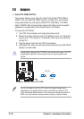
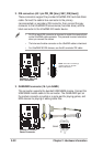
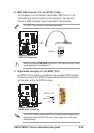
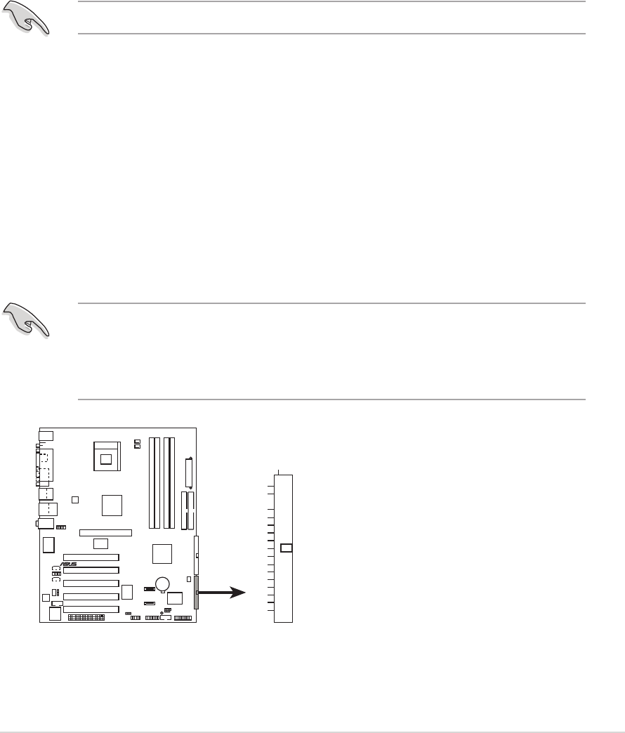
1. Floppy disk drive connector (34-1 pin FLOPPY)
This connector supports the provided floppy drive ribbon cable. After
connecting one end to the motherboard, connect the other end to the
floppy drive. (Pin 5 is removed to prevent incorrect insertion when
using ribbon cables with pin 5 plug).
P4R800-V
DELUXE
®
P4R800-V DELUXE
Floppy Disk Drive Connector
NOTE: Orient the red markings o
n
the floppy ribbon cable to PIN 1.
FLOPPY
PIN 1
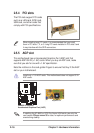
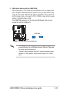
8. USB 2.0 ports 3 and 4. These two 4-pin Universal Serial Bus (USB)
ports are available for connecting USB 2.0 devices.
9. USB 2.0 ports 1 and 2. These two 4-pin Universal Serial Bus (USB)
ports are available for connecting USB 2.0 devices.
10. VGA port. This port connects a VGA compatible monitor.
11. S-Video port. This port connects a television or VCR via an S-Video
cable.
12. Composite video port. This port connects a television via a composite
video cable.
13. PS/2 keyboard port. This purple connector is for a PS/2 keyboard.
The S-Video and RCA ports may not be used simultaneously.