


2-13550-A2-GB20-10 February 1995
Installing the Model 3550 DSU
Overview 2-1. . . . . . . . . . . . . . . . . . . . . . . . . . . . . . . . . . . . . . . . . . . . . . . . . . . . . . . . . . . . . . . . . . . . . . . . . .
Before You Begin 2-1. . . . . . . . . . . . . . . . . . . . . . . . . . . . . . . . . . . . . . . . . . . . . . . . . . . . . . . . . . . . . . . . . . .
How to Change Hardware Straps 2-2. . . . . . . . . . . . . . . . . . . . . . . . . . . . . . . . . . . . . . . . . . . . . . . . . . . . . . .
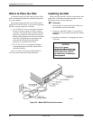
Where to Place the DSU 2-4. . . . . . . . . . . . . . . . . . . . . . . . . . . . . . . . . . . . . . . . . . . . . . . . . . . . . . . . . . . . . .
Installing the DSU 2-4. . . . . . . . . . . . . . . . . . . . . . . . . . . . . . . . . . . . . . . . . . . . . . . . . . . . . . . . . . . . . . . . . . .
Power-Up Routine 2-5. . . . . . . . . . . . . . . . . . . . . . . . . . . . . . . . . . . . . . . . . . . . . . . . . . . . . . . . . . . . . . . .
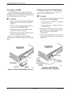
Connecting to the Network 2-5. . . . . . . . . . . . . . . . . . . . . . . . . . . . . . . . . . . . . . . . . . . . . . . . . . . . . . . . . . . .
Connecting to the NMS 2-6. . . . . . . . . . . . . . . . . . . . . . . . . . . . . . . . . . . . . . . . . . . . . . . . . . . . . . . . . . . .
Connecting to the Dial (or PSTN) Network 2-6. . . . . . . . . . . . . . . . . . . . . . . . . . . . . . . . . . . . . . . . . . . .
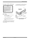
Connecting to the DDS (or LADS) Network 2-7. . . . . . . . . . . . . . . . . . . . . . . . . . . . . . . . . . . . . . . . . . .
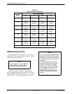
Addressing the Unit 2-8. . . . . . . . . . . . . . . . . . . . . . . . . . . . . . . . . . . . . . . . . . . . . . . . . . . . . . . . . . . . . . . . .
Tributary DSU Addressing 2-9. . . . . . . . . . . . . . . . . . . . . . . . . . . . . . . . . . . . . . . . . . . . . . . . . . . . . . . . .
Connecting the DSU to a DTE 2-10. . . . . . . . . . . . . . . . . . . . . . . . . . . . . . . . . . . . . . . . . . . . . . . . . . . . . . . . .
Connecting Port 2 2-11. . . . . . . . . . . . . . . . . . . . . . . . . . . . . . . . . . . . . . . . . . . . . . . . . . . . . . . . . . . . . . . .
Verifying Operation and Testing Connections 2-11. . . . . . . . . . . . . . . . . . . . . . . . . . . . . . . . . . . . . . . . . . . . .
Verifying Network Addresses 2-11. . . . . . . . . . . . . . . . . . . . . . . . . . . . . . . . . . . . . . . . . . . . . . . . . . . . . . .
Verifying the Network 2-11. . . . . . . . . . . . . . . . . . . . . . . . . . . . . . . . . . . . . . . . . . . . . . . . . . . . . . . . . . . . .
Verifying DBM Operation 2-12. . . . . . . . . . . . . . . . . . . . . . . . . . . . . . . . . . . . . . . . . . . . . . . . . . . . . . . . . .
Verifying TDM/Flex Operation 2-12. . . . . . . . . . . . . . . . . . . . . . . . . . . . . . . . . . . . . . . . . . . . . . . . . . . . . .
Other Tests 2-12. . . . . . . . . . . . . . . . . . . . . . . . . . . . . . . . . . . . . . . . . . . . . . . . . . . . . . . . . . . . . . . . . . . . . .
Overview
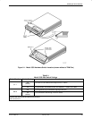
The Model 3550 DSU is designed for desktop
operation and is delivered ready to connect to the
network. It is configured as a tributary DSU for operation
at 9.6 kbps on a multipoint circuit.
If the unit was ordered with a TDM/Flex installed,
Ports 1 and 2 are configured for 9.6 kbps operation, and
configured as a digital sharing device (DSD). Both ports
are configured for EIA-232 operation, rather than V.35
operation. Refer to the MUX (Port) option set tables in
Chapter 5 to change this configuration on a port-by-port
basis.
Installation consists of the following steps, which
should be performed in the order listed.
• Physical installation
• Hardware straps
• Electrical connection
• Network diagnostic connection
• Software configuration
• DDS network (or LADS) connection
• Dial (or PSTN) network connection if a DBM is
installed, or if using an external dial backup unit
(DBU)
• DSU DTE connection
• Verification testing
Although the Model 3550 DSU is designed for desk or
table-top operation, you can order an ACCULINK
3100 Series CSU wall-mount adapter if you want to
mount the DSU on a wall, an equipment shelf, a 19-inch
RS-310-C or 23-inch AT&T DATAPHONE equipment
cabinet. Refer to Appendix F to order the adapter.
Before You Begin
Your installation site should be clean, well-lighted,
well-ventilated, and free from environmental extremes.
A dedicated grounded ac outlet that is protected by a
circuit breaker should be installed within 6 feet of the
DSU’s planned location. The outlet should be capable of
supplying 90 to 132 Vac 60 Hz (U.S. and Canada). The
2