


COMSPHERE 3550 Series Data Service Units
3-2 February 1995 3550-A2-GB20-10
Before You Begin
The COMSPHERE 3000 Series Carrier should already
be installed properly and be operational, with a
functioning shared diagnostic control panel (SDCP). An
SDCP (installed in the carrier) is required for installation
and maintenance of the Model 3551 DSU. For installation
information, see the COMSPHERE 3000 Series Carrier,
Installation Manual.
A fan module may also be needed to dissipate heat.
Refer to the Fan Module Installation section in Chapter 3
of the COMSPHERE 3000 Series Carrier, Installation
Manual to determine whether a fan is required.
The distance between your DTE and the DSU must be
within EIA-232-D/V.24 or V.35 limits.
• For the EIA-232 connector, the typical maximum
distance is 50 feet at speeds less than or equal to
19.2 kbps. If a longer distance is needed, use high
quality, low capacitance cable and ensure that the
effective shunt capacitance of the circuit (measured
at the DSU and including the capacitance of the
cable and the DTE) does not exceed 2500
picofarads, as specified in EIA-232-D.
• For the V.35 connector, the recommended
maximum distance between a DTE and DSU is
nominally 1000 feet.
Before connecting the DSU, you need to contact the
telephone company to coordinate your installation before
connecting the DSU to their network. The DSU can only
be operated at the data rate for which access to the DDS
network is provided. If a DBM is installed, the DSU must
also be connected to the dial network. You must notify the
telephone company before you connect to the dial
network. Refer to the notice at the front of this guide to
ensure compliance with FCC, Bell Canada, and Canadian
DOC rules.
How to Change
Hardware Straps
HANDLING PRECAUTIONS
FOR
STATIC SENSITIVE DEVICES
AT&T Paradyne products are
designed to protect sensitive
components from damage due to
electrostatic discharge (ESD)
during normal operation. When
performing installation
procedures, however, take
proper static control precautions
to prevent damage to
equipment. If you are not sure of
the proper static control
precautions, contact the nearest
AT&T Paradyne Customer
Support office.
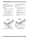
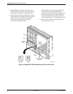
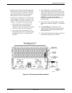
The Model 3551 DSU has several hardware straps that
control the permissive or programmable connection when
a DBM is installed, the Test Mode Indication leads, and
the external interface leads (used with a –48 Vdc Central
Office Power Unit).
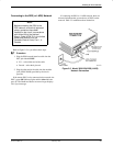
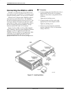
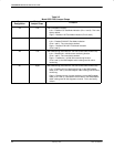
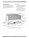
Refer to Figure 3-1 to locate the switch and jumper
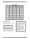
locations. If a DBM is installed, refer to Table 3-1 to
determine which switch needs to be changed, if any. Refer
to Table 3-2 to determine whether these jumper straps
need to be changed.