


Installing the Model 3551 DSU
3-113550-A2-GB20-10 February 1995
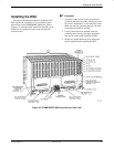
To Connect the SDCP to a DSU
For the carrier-mounted Model 3551 DSU, the SDCP
must first be reconnected to the DSU. Once connected, the
SDCP operates like a DCP.
Procedure
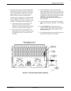
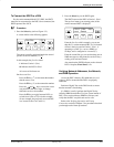
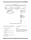
1. Press the Select key (refer to Figure 3-2).
A screen similar to the following appears.
F1 F2
F3
Carr:Slot: 1: 01 A
1:02A
The cursor is usually positioned under the second
position of the slot number (1:01
).
In this example, the first line shows
1 indicates Carrier 1 (Carr)
01 indicates the DSU in Slot 1
A is reserved for future use
On the second line
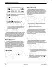
Press the F1 key (↑) to increment the number
that the cursor is on.
Press the F2 key (↓) to decrement the number.
Press the
and keys to move the cursor
one position to the left or right, to change
either the carrier or slot number.
Press the F3 key to toggle between DSUs, to
switch from 1:01A to 1:02A in this example.
(In our example, the previously accessed DSU
was located in Slot 2 of Carrier 1.)
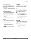
2. Press the Select key on the SDCP again.
The SDCP accesses the DSU in Carrier 1, Slot 1.
The top-level menu (your starting point) of the
carrier-mounted DSU is displayed.
F1
1:01A DSU 9.6 C
Local Remot
F2
F3
From the first line of this example, you can see
that this is a carrier-mounted DSU (1:01A instead
of Port1) that is located in Carrier 1, Slot 1, is
operating as a DSU (i.e., not as a DBM), at
9.6 kbps, and is configured as a control (C).
From the second line you can see that there are no
NMS messages (no Msg branch over the F3 key)
waiting to be read and cleared.
Also note that the SDCP indicator on the selected
DSU’s faceplate, Front Panel, is lit.
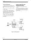
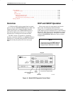
Verifying Network Addresses, the Network,
and DBM Operation
Access the DSU’s identity (ID) subbranch for each
tributary DSU to ensure that the DSUs are properly
addressed.
Perform a Digital Test on the DDS circuit to ensure
that the network is functioning.
If a DBM is installed, perform the Digital Test by
selecting DBM from the Run Test from screen instead of
DSU. Next, test the tributary DBM for dial tone, and
verify that the DSU can place and receive calls.
Refer to the Verifying Operation and Testing
Connections section of Chapter 2 for procedures that lead
you through each of these procedures.