


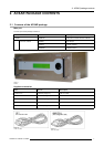
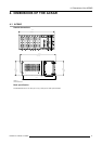


5. Mounting the ACSAR into the Console
5.2 Connecting the ACSAR to console
Which connections have to be made:
• Power connection.
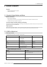
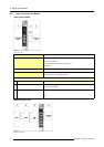
AC Power Voltage
Auto Range 100 – 240V
AC Power Current 1A/50–60Hz
Main Fuses
Standby Power Supply: T 2AH/250V
Main Power Supply: F 4A L 250V
Power Consumption
Normal operation mode 78 W
Depending on input configuration
Standby mode
8W
Economic standby mode 4W
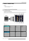
• RS 232 communication between ACSAR, Touch panel and Digital Head.
• DVI link between DVI output ACSAR and DVI input Digital Head.
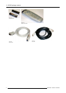
Necessary parts
A RS232 communication, a DVI link and a power cable (type CEE C13), added to the ACSAR unit.
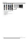
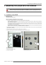
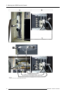
How to connect the ACSAR unit to the console
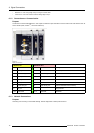
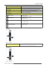
1. Plug the female connector (1) of the power cord (CEE C13 2M5) (C) into the male connector on the power input board of the
ACSAR. Make sure that the power cord plug is firmly inserted into the AC socket. (image 5-6)
2. Plug the male connector (2) into a free
AC socket on the outlet strip in the console.
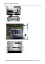
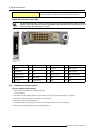
3. Interrupt, in the exiting connection, the control link between Touch panel and Digital Head by pulling out D-9 plug (1) on Touch
panel interface board and reinserting it in the RS232 OUT socket (2) on the communication module of the ACSAR (Link B).
(image 5-7)
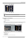
4. Install communication link (A) between RS232 IN (3) on the communication module of the ACSAR and the interface board (1) of
the Touch panel, using the added D9-D9 serial data cable (image 5-7).
5. Install the DVI link (C) between DVI Output (6) on the communication module of the ACSAR and DVI Input (5) on the input panel
of the Digital Head, using the added DVI cable (image 5-7).
Note: The DVI cable has to be routed through the cable hole in front of the console.
6. Reinstall the removed covers before operation the D-Cine projector.
R5976519 ACSAR 12122002
15