724-746-5500 | blackbox.com
724-746-5500 | blackbox.com
Page 45
Chapter 4: E2 Controller
4.1.2 User Interface Display Panel
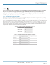
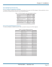
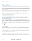
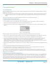
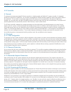
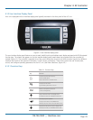
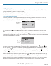
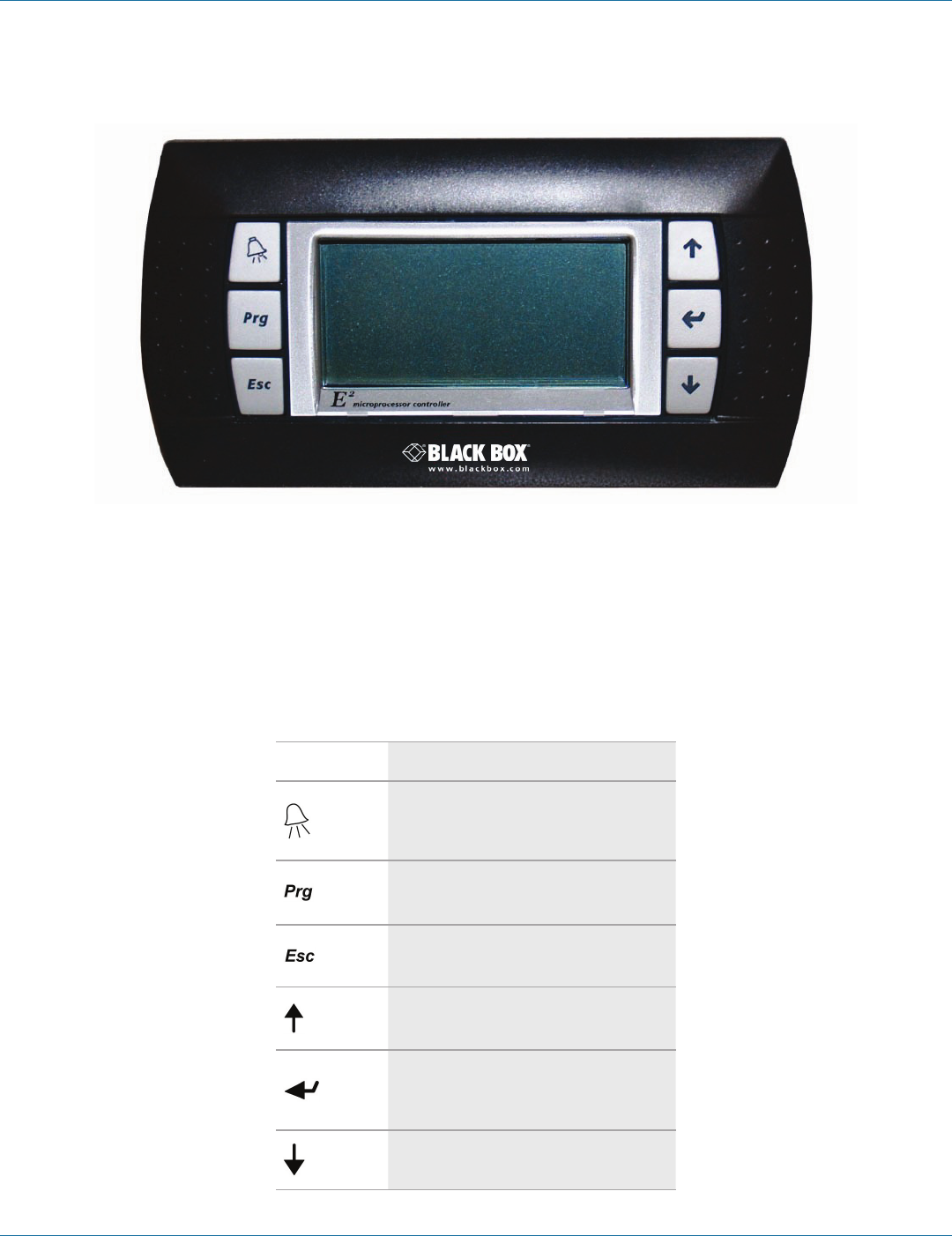
Your unit is equipped with an interface display panel typically mounted on the front panel of the A/C unit.
Figure 4-1. User interface display panel.
The user interface display panel features an easy-to-read, backlit liquid-crystal alphanumeric display equipped with LED illuminated
function keys. The screens that appear on the user interface display panel present data that originates from the controller I/O
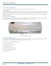
module (Figure 4-1). The controller is operated via a 6-key, menu-driven loop structure and offers an alarm log plus four different
interface menu levels to the operator: Information, Control, Service, and Factory. These menus permit the user to easily view,
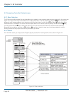
control, and configure operating parameters for the A/C unit. (See Menu Selections, Figure 4-6.)
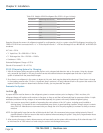
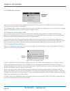
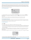
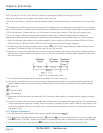
4.1.2.1 Function Keys
Table 4-1. Function keys.
Key Function
Accesses the active alarm screen(s).
Silences audible alarms.
Resets active alarms in the alarm menu.
Accesses the main menu.
Prg Illuminates yellow when unit is on.
Returns to the previous menu level.
Cancels a changed entry.
Steps to the next screen in the display menu.
Increases the value of a modifiable numeric field.
Starts/Stops system operation.
Accepts current value of a modifiable field.
Advances the cursor to the next active alarm screen.
Steps back to the previous screen in display menu.
Decreases the value of a modifiable numeric field.


