


User’s Manual
BOSCH
- 17/77 -
Revision 1.6TTCAN
11.11.02
manual_about.fm
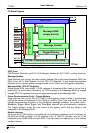
3.2 CAN Protocol Related Registers
These registers are related to the CAN protocol controller in the CAN Core. They control the
operating modes and the configuration of the CAN bit timing and provide status information.
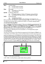
3.2.1 CAN Control Register (addresses 0x01 & 0x00)
Test Test Mode Enable
one
Test Mode.
zero
Normal Operation.
CCE Configuration Change Enable
one
The CPU has write access to the configuration registers (while Init =
one
).
zero
The CPU has no write access to the configuration registers.
DAR Disable Automatic Retransmission
one
Automatic Retransmission disabled.
zero
Automatic Retransmission of not successful messages enabled.
EIE Error Interrupt Enable
one
Enabled - A change in the bits BOff or EWarn in the Status Register will
generate an interrupt.
zero
Disabled - No Error Status Interrupt will be generated.
SIE Status Change Interrupt Enable
one
Enabled - An interrupt will be generated when a message transfer is suc-
cessfully completed or a CAN bus error is detected.
zero
Disabled - No Status Change Interrupt will be generated.
IE Module Interrupt Enable
one
Enabled - Interrupts will set IRQ_B to LOW. IRQ_B remains LOW until all
pending interrupts are processed.
zero
Disabled - Module Interrupt IRQ_B is always HIGH.
Init Initialization
one
Initialization is started.
zero
Normal Operation.
The configuration registers controlled by CCE are the Bit Timing Register, the BRP Extension
Register, and the TT Operation Mode Register.
Note :
The
Bus_Off
recovery sequence (see CAN Specification Rev. 2.0) cannot be shortened by set-
ting or resetting Init. If the device goes
Bus_Off
, it will set Init of its own accord, stopping all bus
activities. Once Init has been cleared by the CPU, the device will then wait for 129 occurrences
of
Bus Idle
(129 * 11 consecutive
recessive
bits) before resuming normal operations. At the end
of the Bus_Off recovery sequence, the Error Management Counters will be reset.
During the waiting time after the resetting of Init, each time a sequence of 11
recessive
bits
has been monitored, a Bit0Error code is written to the Status Register, enabling the CPU to
readily check up whether the CAN bus is stuck at
dominant
or continuously disturbed and to
monitor the proceeding of the Bus_Off recovery sequence.
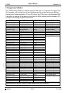
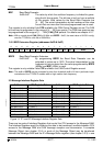
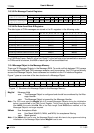
1514131211109876543210
res res res res res res res res Test CCE DAR res EIE SIE IE Init
rrrrrrrrrwrwrwrrwrwrwrw