


User’s Manual
BOSCH
- 51/77 -
Revision 1.6TTCAN
11.11.02
manual_about.fm
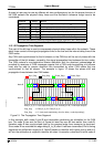
In these bit timing registers, the four components TSEG1, TSEG2, SJW, and BRP have to be
programmed to a numerical value that is one less than its functional value; so instead of
values in the range of [1
…n], values in the range of [0…n-1] are programmed. That way, e.g.
SJW (functional range of [1
…4]) is represented by only two bits.
Therefore the length of the bit time is (programmed values) [TSEG1 + TSEG2 + 3] t
q
or
(functional values) [Sync_Seg + Prop_Seg + Phase_Seg1 + Phase_Seg2] t
q
.
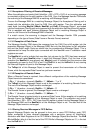
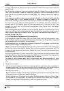
The data in the bit timing registers are the configuration input of the CAN protocol controller.
The Baud Rate Prescaler (configured by BRP) defines the length of the time quantum, the
basic time unit of the bit time; the Bit Timing Logic (configured by TSEG1, TSEG2, and SJW)
defines the number of time quanta in the bit time.
The processing of the bit time, the calculation of the position of the Sample Point, and
occasional synchronisations are controlled by the BTL state machine, which is evaluated once
each time quantum. The rest of the CAN protocol controller, the Bit Stream Processor (BSP)
state machine is evaluated once each bit time, at the Sample Point.
The Shift Register serializes the messages to be sent and parallelizes received messages. Its
loading and shifting is controlled by the BSP.
The BSP translates messages into frames and vice versa. It generates and discards the
enclosing fixed format bits, inserts and extracts stuff bits, calculates and checks the CRC
code, performs the error management, and decides which type of synchronisation is to be
used. It is evaluated at the Sample Point and processes the sampled bus input bit. The time
after the Sample point that is needed to calculate the next bit to be sent (e.g. data bit, CRC bit,
stuff bit, error flag, or idle) is called the Information Processing Time (IPT).
The IPT is application specific but may not be longer than 2 t
q
; the TTCAN’s IPT is 0 t
q
. Its
length is the lower limit of the programmed length of Phase_Seg2. In case of a synchronisa-
tion, Phase_Seg2 may be shortened to a value less than IPT, which does not affect bus timing.
4.2.1.6 Calculation of the Bit Timing Parameters
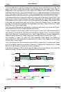
Usually, the calculation of the bit timing configuration starts with a desired bit rate or bit time.
The resulting bit time (1/bit rate) must be an integer multiple of the system clock period.
The bit time may consist of 4 to 25 time quanta, the length of the time quantum t
q
is defined by
the Baud Rate Prescaler with t
q
= (Baud Rate Prescaler)/f
sys
. Several combinations may lead
to the desired bit time, allowing iterations of the following steps.
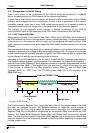
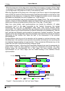
First part of the bit time to be defined is the Prop_Seg. Its length depends on the delay times
measured in the system. A maximum bus length as well as a maximum node delay has to be
defined for expandible CAN bus systems. The resulting time for Prop_Seg is converted into
time quanta (rounded up to the nearest integer multiple of t
q
).
The Sync_Seg is 1 t
q
long (fixed), leaving (bit time – Prop_Seg – 1) t
q
for the two Phase Buffer
Segments. If the number of remaining t
q
is even, the Phase Buffer Segments have the same
length, Phase_Seg2 = Phase_Seg1, else Phase_Seg2 = Phase_Seg1 + 1.
The minimum nominal length of Phase_Seg2 has to be regarded as well. Phase_Seg2 may
not be shorter than the CAN controller’s Information Processing Time, which is, depending on
the actual implementation, in the range of [0
…2] t
q
.
The length of the Synchronisation Jump Width is set to its maximum value, which is the
minimum of 4 and Phase_Seg1.
The oscillator tolerance range necessary for the resulting configuration is calculated by the
formulas given in section 4.2.1.4