


User’s Manual
BOSCH
- 45/77 -
Revision 1.6TTCAN
11.11.02
manual_about.fm
4.2.1 Configuration of the Bit Timing
Even if minor errors in the configuration of the CAN bit timing do not result in immediate
failure, the performance of a CAN network can be reduced significantly.
In many cases, the CAN bit synchronisation will amend a faulty configuration of the CAN bit
timing to such a degree that only occasionally an error frame is generated. In the case of
arbitration however, when two or more CAN nodes simultaneously try to transmit a frame, a
misplaced sample point may cause one of the transmitters to become error passive.
The analysis of such sporadic errors requires a detailed knowledge of the CAN bit
synchronisation inside a CAN node and of the CAN nodes’ interaction on the CAN bus.
4.2.1.1 Bit Time and Bit Rate
CAN supports bit rates in the range of lower than 1 KBit/s up to 1000 kBit/s. Each member of
the CAN network has its own clock generator, usually a quartz oscillator. The timing parameter
of the bit time (i.e. the reciprocal of the bit rate) can be configured individually for each CAN
node, creating a common bit rate even though the CAN nodes’ oscillator periods (f
osc
)maybe
different.
The frequencies of these oscillators are not absolutely stable, small variations are caused by
changes in temperature or voltage and by deteriorating components. As long as the variations
remain inside a specific oscillator tolerance range (df), the CAN nodes are able to compensate
for the different bit rates by resynchronising to the bit stream.
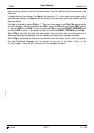
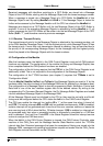
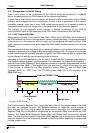
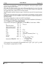
According to the CAN specification, the bit time is divided into four segments (see figure 9).
The Synchronisation Segment, the Propagation Time Segment, the Phase Buffer Segment 1,
and the Phase Buffer Segment 2. Each segment consists of a specific, programmable number
of time quanta (see Table 1). The length of the time quantum (t
q)
, which is the basic time unit
of the bit time, is defined by the CAN controller’s system clock f
sys
and the Baud Rate
Prescaler (BRP): t
q
= BRP / f
sys
. The TTCAN’s system clock f
sys
is the frequency of its
CAN_CLK input.
Figure 9: Bit Timing
The Synchronisation Segment Sync_Seg is that part of the bit time where edges of the CAN
bus level are expected to occur; the distance between an edge that occurs outside of
Sync_Seg and the Sync_Seg is called the phase error of that edge. The Propagation Time
Segment Prop_Seg is intended to compensate for the physical delay times within the CAN
network. The Phase Buffer Segments Phase_Seg1 and Phase_Seg2 surround the Sample
Point. The (Re-)Synchronisation Jump Width (SJW) defines how far a resynchronisation may
move the Sample Point inside the limits defined by the Phase Buffer Segments to compensate
for edge phase errors.
1 Time Quantum
(t
q
)
Sync_ Prop_Seg Phase_Seg1 Phase_Seg2
Sample Point
Nominal CAN Bit Time
Seg