


User’s Manual
BOSCH
- 64/77 -
Revision 1.6TTCAN
11.11.02
manual_about.fm
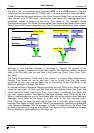
A typical Trigger List for a potential Time Master will begin with a number of Tx_Triggers and
Rx_Triggers followed by the Tx_Ref_Trigger and the Watch_Trigger. For networks with Event
Synchronised Time triggered Communication, this is followed by the Tx_Ref_Trigger_Gap and
the Watch_Trigger_Gap. The Trigger List for a Time Slave will be the same but without the
Tx_Ref_Trigger and the Tx_Ref_Trigger_Gap.
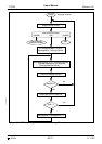
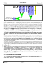
At the beginning of each Basic Cycle, that is at each reception or transmission of a Reference
Message, the Trigger List will be processed starting with the first Trigger Memory word. The
FSE looks for the first Trigger with a Cycle_Code that matches the current Cycle_Count. The
FSE waits until Cycle Time reaches the Trigger’s Time_Mark and activates the Trigger.
Afterwards the FSE looks for the next Trigger in the list with a Cycle_Code that matches the
current Cycle_Count.
A Configuration Error is detected at the following conditions :
When the FSE comes to a Trigger in the list with a Cycle_Code that matches the current
Cycle_Count but with a Time_Mark that is less than Cycle Time.
When the FSE comes to a Trigger in the list with a Cycle_Code that matches the current
Cycle_Count but that is neither Tx_Trigger_Merged nor Tx_Trigger_Single and the previous
active Trigger was a Tx_Trigger_Merged.
When the FSE of a node with TM=‘0’ encounters a Tx_Ref_Trigger or a Tx_Ref_Trigger_Gap.
When the Time_Mark of an Rx_Trigger is placed inside the Tx_Enable Window of a
Tx_Trigger with a matching Cycle_Code or between a Tx_Trigger_Merged and another
Tx_Trigger with a Cycle_Code matching the same Cycle_Count.
When the Time_Mark of an Rx_Trigger is placed near the Time_Mark of a Tx_Ref_Trigger and
the Ref_Trigger_Offset causes a reversal of their sequential order measured in Cycle Time.
5.1.4 Message Objects
The Message Status Count MSC of each Message Object has to be initialised to 0. It can only
be written in “Configuration Mode”. The configuration of Receive Objects for “Time Triggered
Communication” is the same as for “Event driven Communication”, see chapter 4.2.2. Some
differences exist for the configuration of the Reference Message and of Transmit Objects:
5.1.4.1 Reference Message
The first Message Object is reserved for the transmission or reception of the Reference
Message. When a Reference Message is transmitted, the last three bits of the Identifier, the
DLC, and the first data byte (TTCAN Level 1) or the first three data bytes (TTCAN Level 2) will
be provided by the FSE, the rest of the Reference Message is provided by the first Message
Object. The first Message Object requires the following configuration: The Identifier and the
Data Length Code of the Reference Message including IDE bit, MsgVal=‘1’, NewDat=‘1’,
TxRqst=‘0’, UMask=‘1’, EoB=‘1’, Dir=‘1’, MDir=‘0’. When the Reference Message uses an
Extended Identifier, Msk=0x1FFFFFF8, else Msk=0x1FE3FFFF. The MSC of the first
Message Object will not be updated.
5.1.4.2 Periodic Transmit Message
The Message Objects for periodic transmit messages may not be managed dynamically, each
Tx_Trigger in the Trigger Memory points to a particular Message Object containing a specific
message. There may be more than one Tx_Trigger for a given Message Object, if that
Message Object contains a message that is to be transmitted more than once in a Basic Cycle
or Matrix Cycle. The configuration has to define MsgVal=‘1’, RmtEn=‘0’, TxRqst=‘0’,
UMask=‘0’, EoB=‘1’, Dir=‘1’, MDir=‘0’, MSC=0, the identifier, the IDE bit, and the DLC.