


User’s Manual
BOSCH
- 32/77 -
Revision 1.6TTCAN
11.11.02
manual_about.fm
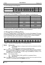
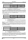
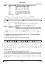
CCM Cycle_Count_Max (Number of last Basic Cycle in the Matrix Cycle)
0x00
1 Basic Cycle in the Matrix Cycle.
0x01
2 Basic Cycles in the Matrix Cycle.
0x03
4 Basic Cycles in the Matrix Cycle.
0x07
8 Basic Cycles in the Matrix Cycle.
0x0F
16 Basic Cycles in the Matrix Cycle.
0x1F
32 Basic Cycles in the Matrix Cycle.
0x3F
64 Basic Cycles in the Matrix Cycle.
other values
reserved.
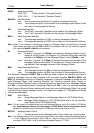
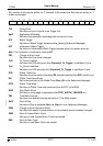
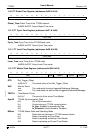
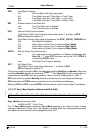
3.5.6 TT Application Watchdog Limit Register (addresses 0x2F & 0x2E)
Bark The state of the Application_Watchdog
one
The application has failed to serve the watchdog on time.
zero The application did serve the watchdog on time.
AppWdL Application_Watchdog_Limit
0x00-0xFF
The maximum time (unit is 256•NTU) after which the application
has to serve the watchdog again since last time it has served it.
The application watchdog is served by reading the high byte of the register. When the
watchdog is not served in time, the bit Bark is set, all TTCAN communication is stopped, and
the TTCAN module is set into silent mode. The TTCAN module is restarted by writing Bark to
‘0’ in configuration mode.
The application watchdog can be disabled by programming the Test Register bit WdOff to ‘1’
and AppWdL to 0x00, see chapter 2.3.4.2.
3.5.7 TT Interrupt Enable Register (addresses 0x31 & 0x30)
There is for each bit in the TT Interrupt Vector register one corresponding enable bit in the TT
Interrupt Enable register, ‘1’ meaning enabled and ‘0’ meaning disabled. The TT Interrupt
Vector register bits will be updated regardless of the TT Interrupt Enable register bits, the
enable bits control whether an interrupt will be generated when the matching bit in the TT
Interrupt Vector register is set to ‘1’ (and when the module interrupt is enabled by IE = ‘1’ in the
CAN Control register).
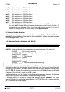
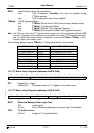
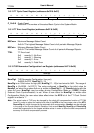
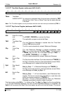
3.5.8 TT Interrupt Vector Register (addresses 0x33 & 0x32)
The individual TT Interrupt Vector register bits are set to ‘1’ when their specific interrupt
condition is met, an interrupt will be generated as long as both an Interrupt Vector bit and the
corresponding Interrupt Enable bits are set. The Interrupt Vector register bits will not be
cleared automatically; with the exception of hardware reset, they can only be cleared by the
CPU. The CPU cannot write the Interrupt Vector register bits to ‘1’, but it can write them to ‘0’.
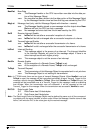
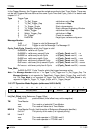
15 14 13 12 11 10 9 8 7 6 5 4 3 2 1 0
Bark res AppWdL
rw r rw
15 14 13 12 11 10 9 8 7 6 5 4 3 2 1 0
CfE ApW WTr IWT CEL TxO TxU GTE Dis GTW SWE TMI SoG CSM SSM SBC
rw rw rw rw rw rw rw rw rw rw rw rw rw rw rw rw