


User’s Manual
BOSCH
- 70/77 -
Revision 1.6TTCAN
11.11.02
manual_about.fm
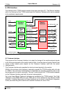
The TT Interrupt Vector consists of four segments, each four bits long. Each of the bits of the
TT Interrupt Vector can be separately enabled by a corresponding bit in the TT Interrupt
Enable register. Once a bit of the TT Interrupt Vector is set, it will remain set until the
application program writes a ‘0’ to this bit.
The first segment consists of CfE, ApW, Wtr, and IWT. Each of these interrupts indicates a
fatal error condition where the CAN communication is stopped. With the exception of IWT (see
chapter 5.2), these error conditions require a re-configuration of the TTCAN module before the
communication can be restarted.
The second segment consists of CEL, TxO, TxU, and GTE. Each of these interrupts indicates
an error condition where the CAN communication is disturbed. If they are caused by a
transient failure, e.g. by disturbance on the CAN bus, they will be handled by the TTCAN
protocol’s failure handling and do not require intervention by the application program.
The third segment consists of Dis, GTW, SWE, and TMI. The first two interrupts are caused by
Global Time events (Level 2 only) that require a reaction by the application program. The Stop
Watch Event and the Time Mark Interrupt provide feedback to the application program when
the application has requested the timing of external events or the notification on reaching a
specific time. The Time Mark Interrupt can also be used to finish a Gap.
The fourth segment consists of Gap, CSM, SSM, and SBC. These interrupts provide a means
to synchronise the application program to the communication schedule.
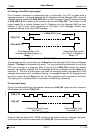
5.8 Configuration Example
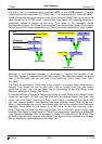
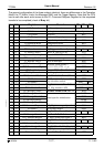
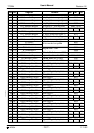
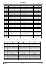
This is a configuration example for a TTCAN system consisting of three nodes (M0, M1, and
S0) operating in TTCAN level 2 at a bit rate of 1 MBit/s. All three nodes have a system clock
frequency of 10 MHz, the network time unit NTU is 1µs. Two nodes (M0 and M1) are potential
time masters, the third node S0 is operating as a time slave.
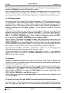
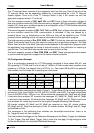
The System Matrix consists of four Basic Cycles 0…3, each Basic Cycle has five transmission
columns at Cycle Time 0x00A0, 0x0140, 0x01E0, 0x0280, and 0x320. The length of the Basic
Cycle is 0x03E8 NTUs=1000µs=1ms. M0 transmits the messages M0_Msg2 and M0_Msg3
in exclusive time windows. M1 transmits the messages M1_Msg2, M1_Msg3, and M1_Msg4
in exclusive time windows. S0 transmits the messages S0_Msg2 and S0_Msg3 in exclusive
time windows. All nodes may transmit in the single or merged arbitrating time windows.
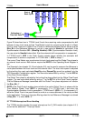
M0 checks whether M1_Msg2 and S0_Msg2 are received on time. M1 checks whether
M0_Msg3 and S0_Msg3 are received on time. S0 checks whether M0_Msg2 and M1_Msg4
are received on time.
The messages in the arbitrating time windows are transmitted event-driven, there is no
Rx_Trigger to check for their reception.
The time between the trigger for the Reference Message and the Watch_Trigger (and between
Tx_Ref_Trigger_Gap and Watch_Trigger_Gap in case of a time gap) is long enough to allow
for the retransmission of a disturbed Reference Message.
0x00A0 0x0140 0x01E0 0x0280 0x0320 0x03E6 0x0540 0x2000 0x2200
0 M0_Msg2 S0_Msg2 M1_Msg2 Merged_Arb_Win
Ref_Msg Watch Ref_Gap Watch_Gap
1 S0_Msg3 S0_Msg2 M0_Msg3 M1_Msg3 Arb_Win1
2 M0_Msg2 S0_Msg2 M1_Msg2 Arb_Win2 M1_Msg4
3 S0_Msg3 S0_Msg2 M0_Msg3 M1_Msg3 Arb_Win3