


User’s Manual
BOSCH
- 77/77 -
Revision 1.6TTCAN
11.11.02
manual_about.fm
7. Appendix
7.1 List of Figures
Figure 1: Block Diagram of the TTCAN . . . . . . . . . . . . . . . . . . . . . . . . . . . . . . . . . . . . . . . .9
Figure 2: CAN_Core in Silent Mode . . . . . . . . . . . . . . . . . . . . . . . . . . . . . . . . . . . . . . . . . . 12
Figure 3: CAN_Core in Loop Back Mode . . . . . . . . . . . . . . . . . . . . . . . . . . . . . . . . . . . . . . 13
Figure 4: CAN_Core in Loop Back combined with Silent Mode . . . . . . . . . . . . . . . . . . . . . 13
Figure 5: TTCAN Register Summary . . . . . . . . . . . . . . . . . . . . . . . . . . . . . . . . . . . . . . . . . 16
Figure 6: IF1 and IF2 Message Interface Register Sets. . . . . . . . . . . . . . . . . . . . . . . . . . .20
Figure 7: Structure of a Message Object in the Message Memory. . . . . . . . . . . . . . . . . . .24
Figure 8: Data Transfer between IFx Registers and Message RAM . . . . . . . . . . . . . . . . .42
Figure 9: Bit Timing. . . . . . . . . . . . . . . . . . . . . . . . . . . . . . . . . . . . . . . . . . . . . . . . . . . . . . .45
Figure 10: The Propagation Time Segment . . . . . . . . . . . . . . . . . . . . . . . . . . . . . . . . . . . . . 46
Figure 11: Synchronisation on “late” and “early” Edges . . . . . . . . . . . . . . . . . . . . . . . . . . . .48
Figure 12: Filtering of Short Dominant Spikes . . . . . . . . . . . . . . . . . . . . . . . . . . . . . . . . . . . 49
Figure 13: Structure of the CAN Core’s CAN Protocol Controller. . . . . . . . . . . . . . . . . . . . . 50
Figure 14: Initialisation of a Transmit Object . . . . . . . . . . . . . . . . . . . . . . . . . . . . . . . . . . . . 54
Figure 15: Initialisation of a single Receive Object. . . . . . . . . . . . . . . . . . . . . . . . . . . . . . . . 54
Figure 16: Initialisation of a single Receive Object. . . . . . . . . . . . . . . . . . . . . . . . . . . . . . . . 55
Figure 17: CPU Handling of a FIFO Buffer (Interrupt Driven). . . . . . . . . . . . . . . . . . . . . . . . 59
Figure 18: TUR configuration examples . . . . . . . . . . . . . . . . . . . . . . . . . . . . . . . . . . . . . . . .61
Figure 19: Cycle Time and Global Time Synchronisation. . . . . . . . . . . . . . . . . . . . . . . . . . . 68
Figure 20: TTCAN Level 2 Drift Compensation . . . . . . . . . . . . . . . . . . . . . . . . . . . . . . . . . .69
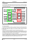
Figure 21: Structure of the module interface . . . . . . . . . . . . . . . . . . . . . . . . . . . . . . . . . . . . 75
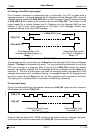
Figure 22: Timing of WAIT output signal CAN_WAIT_B. . . . . . . . . . . . . . . . . . . . . . . . . . . .76
Figure 23: Timing of interrupt signal CAN_INT. . . . . . . . . . . . . . . . . . . . . . . . . . . . . . . . . . .76
EOF
manual_appendix.fm