


User’s Manual
BOSCH
- 50/77 -
Revision 1.6TTCAN
11.11.02
manual_about.fm
4.2.1.4 Oscillator Tolerance Range
The oscillator tolerance range was increased when the CAN protocol was developed from
version 1.1 to version 1.2 (version 1.0 was never implemented in silicon). The option to
synchronise on edges from dominant to recessive became obsolete, only edges from
recessive to dominant are considered for synchronisation. The only CAN controllers to
implement protocol version 1.1 have been Intel 82526 and Philips 82C200, both are
superseded by successor products. The protocol update to version 2.0 (A and B) had no
influence on the oscillator tolerance.
The tolerance range df for an oscillator’s frequency f
osc
around the nominal frequency f
nom
with depends on the proportions of Phase_Seg1, Phase_Seg2,
SJW, and the bit time. The maximum tolerance df is the defined by two conditions (both shall
be met):
It has to be considered that SJW may not be larger than the smaller of the Phase Buffer
Segments and that the Propagation Time Segment limits that part of the bit time that may be
used for the Phase Buffer Segments.
The combination Prop_Seg = 1 and Phase_Seg1 = Phase_Seg2 = SJW = 4 allows the
largest possible oscillator tolerance of 1.58%. This combination with a Propagation Time
Segment of only 10% of the bit time is not suitable for short bit times; it can be used for bit
rates of up to 125 kBit/s (bit time = 8 µs) with a bus length of 40 m.
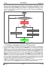
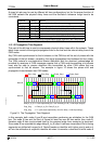
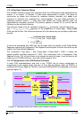
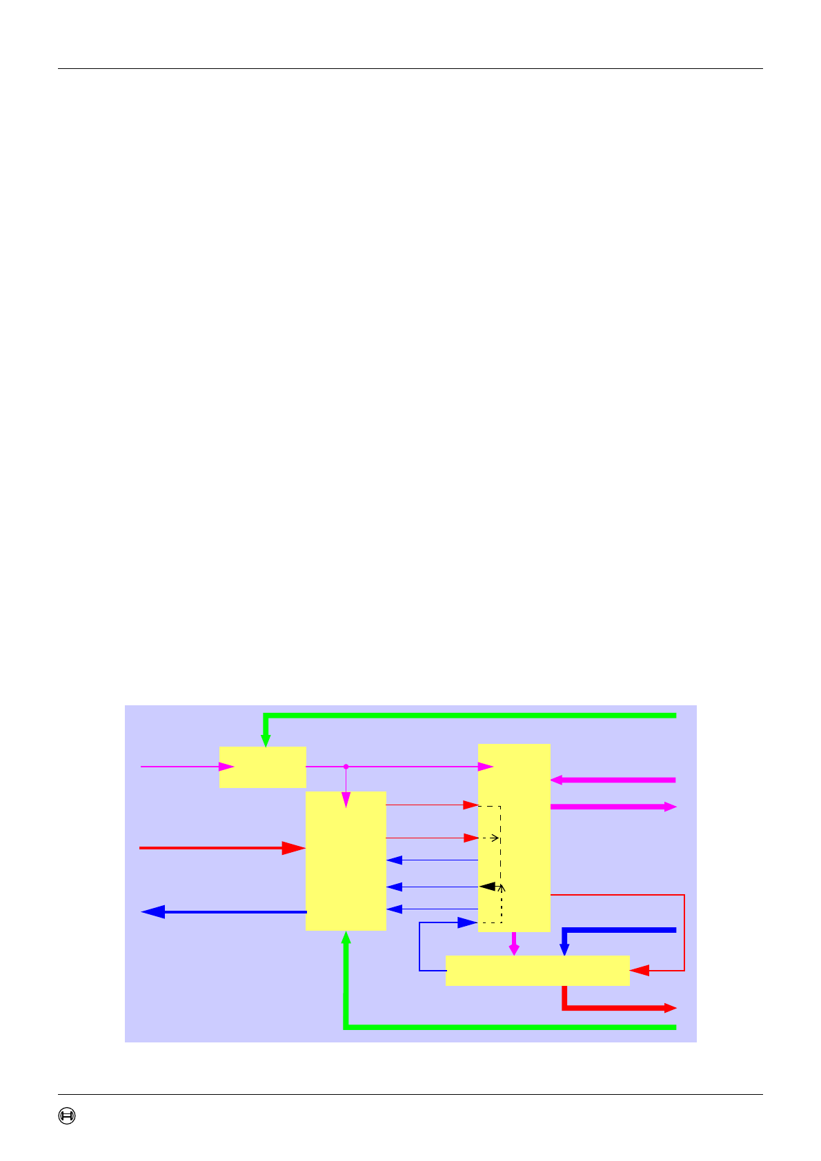
4.2.1.5 Configuration of the CAN Protocol Controller
In most CAN implementations and also in the TTCAN, the bit timing configuration is
programmed in two register bytes. The sum of Prop_Seg and Phase_Seg1 (as TSEG1) is
combined with Phase_Seg2 (as TSEG2) in one byte, SJW and BRP are combined in the other
byte (see figure 13).
Figure 13: Structure of the CAN Core’s CAN Protocol Controller
1df–()f
nom
• f
osc
1df+()f
nom
•≤≤
I: df
min
Phase_Seg1 Phase_Seg2,()
2 13 bit_time Phase_Seg2–•()•
---------------------------------------------------------------------------------------
≤
II: df
SJW
20 bit_time•
---------------------------------
≤
Sample_Point
Bit_to_send
Sync_Mode
Bus_Off
Scaled_Clock (t
q
)
System Clock
Receive_Data
Transmit_Data
Control
Received_Message
Send_Message
Status
Bit
Timing
Logic
Baudrate_
Prescaler
Sampled_Bit
Configuration (TSEG1, TSEG2, SJW)
Configuration (BRP)
Shift-Register
Received_Data_Bit
Next_Data_Bit
Control
Bit Stream Processor
IPT