


User’s Manual
BOSCH
- 9/77 -
Revision 1.6TTCAN
11.11.02
manual_about.fm
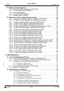
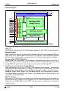
2.2 Block Diagram
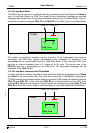
Figure 1: Block Diagram of the TTCAN
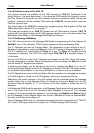
CAN_Core
CAN Protocol Controller and Rx/Tx Shift Register, handles all ISO 11898-1 protocol functions.
Message Handler
State Machine that controls the data transfer between the single ported Message RAM, the
CAN_Core’s Rx/Tx Shift Register, and the CPU IFC Registers. It also handles acceptance
filtering and the interrupt setting as programmed in the Control and Configuration Registers.
Message RAM / CPU IFC Registers
Single ported RAM, word-length = [CAN message & acceptance filter mask & control bits &
status bits]. To ensure data consistency, all CPU accesses to the Message RAM are relayed
through CPU IFC registers that have the same word-length as the Message RAM.
Frame Synchronisation Entity / Trigger Memory
State machine that controls the ISO 11898-4 time triggered communication. It synchronises
itself to the reference messages on the CAN bus, controls Cycle Time and Global Time, and
handles transmissions according to the predefined message schedule, the system matrix.
StopWatch Trigger, EVent Trigger, and Time Mark Interrupt are synchronisation interfaces.
The Trigger Memory stores the time marks of the system matrix that are linked to the
messages in the Message RAM.
Module Interface
Up to now the TTCAN module is provided with three different interfaces. An 8-bit interface for
the Motorola HC08 controller a 16-bit interface to the TI TMS470 controller, and two 16-bit
interfaces to the AMBA APB bus from ARM. They can easily be replaced by a user-defined
module interface.
DataIN
Clock
Reset
Address
Control
Wait
DataOUT
Interrupt
TMI
SWT, EVT
Message Handler
Message RAM
Trigger Memory
TTCAN - Frame Synchronisation Entity
CAN_TX
CAN_RX
CAN_Core
CPU IFC Register 2
CPU IFC Register 1
Module Interface
(single ported)
CAN-Message
Trigger
TTCAN