


User’s Manual
BOSCH
- 53/77 -
Revision 1.6TTCAN
11.11.02
manual_about.fm
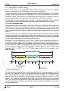
4.2.1.8 Example for Bit Timing at low Baudrate
In this example, the frequency of CAN_CLK is 2 MHz, BRP is 1, the bit rate is 100 KBit/s.
t
q
1 µs=2•t
CAN_CLK
delay of bus driver 200 ns
delay of receiver circuit 80 ns
delay of bus line (40m) 220 ns
t
Prop
1 µs=1•t
q
t
SJW
4 µs=4•t
q
t
TSeg1
5 µs=t
Prop
+ t
SJW
t
TSeg2
4 µs = Information Processing Time + 3 • t
q
t
Sync-Seg
1 µs=1•t
q
bit time 10 µs=t
Sync-Seg
+ t
TSeg1
+ t
TSeg2
tolerance for CAN_CLK 1.58 % =
=
In this example, the concatenated bit time parameters are (4-1)
3
&(5-1)
4
&(4-1)
2
&(2-1)
6
, the Bit
Timing Register is programmed to= 0x34C1.
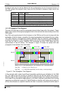
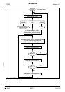
4.2.2 Configuration of the Message Memory
The whole Message Memory has to be configured before the end of the initialisation, but is
also possible to change the configuration of Message Objects during CAN communication.
The CAN software driver library should offer subroutines that:
• Transfer a complete message structure into a Message Object. (Configuration)
• Transfer the data bytes of a message into a Message Object and set TxRqst and NewDat.
(Start a new transmission)
• Get the data bytes of a message from a Message Object and clear NewDat (and IntPnd).
(Read received data)
• Get the complete message from a Message Object and clear NewDat (and IntPnd).
(Read a received message, including identifier, from a Message Object with UMask = ‘1’)
Parameters of the subroutines are the Message Number and a pointer to a complete
message structure or to the data bytes of a message structure.
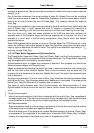
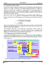
Two methods are possible to assign the IFx Interface Register sets to these subroutines. In the
first method, the tasks of the application program that may access the module are assorted in
two groups. Each group is restricted to the use of one of the Interface Register sets. The tasks
of one group may interrupt tasks of the other group, but not of the same group.
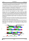
In the second method, which may be a special case of the first method, there are only two
tasks is the application program that access the module. A Read_Message task that uses
IFC1 to get received messages (full messages or data bytes only) from the Message RAM and
a Write_Message task that uses IFC2 to write messages to be transmitted (or to be
configured) into the Message RAM. Both tasks may interrupt each other.
The CAN communication may be controlled interrupt-driven or by polling. The module’s
Interrupt Register points to Message Objects with IntPnd = ‘1’. It is updated even if the
interrupt line to the CPU is disabled (IE = ‘0’).
min PB
1
PB
2,()
2 13 bit time
PB
2–×()×
-----------------------------------------------------------------
4µ
s
21310µ
s
4µ
s
–×()×
----------------------------------------------------------