


User’s Manual
BOSCH
- 21/77 -
Revision 1.6TTCAN
11.11.02
manual_about.fm
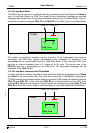
single transfer. This transfer, performed in parallel on all selected parts of the Message Object,
guarantees the data consistency of the CAN message. Figure 6 shows the structure of the two
Interface Register sets.
The function of the two Interface Register sets is identical (except for test mode NoRAM). The
second interface register set is provided to serve application programming. Two groups of
software drivers may defined, each group is restricted to the use of one of the Interface
Register sets. The software drivers of one group may interrupt software drivers of the other
group, but not of the same group.
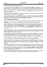
In a simple example, there is one Read_Message task that uses IFC1 to get received
messages from the Message RAM and there is one Write_Message task that uses IFC2 to
write messages to be transmitted into the Message RAM. Both tasks may interrupt each other.
Each set of Interface Registers consists of Message Buffer Registers controlled by their own
Command Registers. The Command Mask Register specifies the direction of the data transfer
and which parts of a Message Object will be transferred. The Command Request Register is
used to select a Message Object in the Message RAM as target or source for the transfer and
to start the action specified in the Command Mask Register.
3.3.1 IFx Command Mask Registers
The control bits of the IFx Command Mask Register specify the transfer direction and select
which of the IFx Message Buffer Registers are source or target of the data transfer.
WR/RD Write / Read
one
Write: Transfer data from the selected Message Buffer Registers to the
Message Object addressed by the Command Request Register.
zero
Read: Transfer data from the Message Object addressed by the Com-
mand Request Register into the selected Message Buffer Registers.
The other bits of IFx Command Mask Register have different functions depending on the
transfer direction :
3.3.1.1 Direction = Write
Mask Access Mask Bits
one
transfer Identifier Mask + MDir + MXtd to Message Object.
zero
Mask bits unchanged.
Arb Access Arbitration Bits
one
transfer Identifier + Dir + Xtd + MsgVal to Message Object.
zero
Arbitration bits unchanged.
Control Access Control Bits
one
transfer Control Bits to Message Object.
zero
Control Bits unchanged.
Note :
MSC2-0 is read-only in time triggered operating mode.
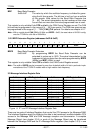
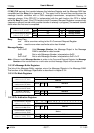
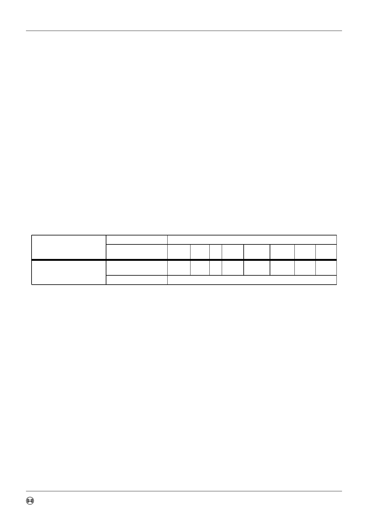
IF1 Command Mask Register
(addresses 0x13 & 0x12)
15 14 13 12 11 10 9 8 7 6 5 4 3 2 1 0
res WR/RD Mask Arb Control
ClrIntPnd
TxRqst/
NewDat
Data A Data B
IF2 Command Mask Register
(addresses 0x43 & 0x42)
res WR/RD Mask Arb Control
ClrIntPnd
TxRqst/
NewDat
Data A Data B
r r r r r r r r rw rw rw rw rw rw rw rw