


User’s Manual
BOSCH
- 48/77 -
Revision 1.6TTCAN
11.11.02
manual_about.fm
When the phase error of the edge which causes Resynchronisation is negative, Phase_Seg2
is shortened. If the magnitude of the phase error is less than SJW, Phase_Seg2 is shortened
by the magnitude of the phase error, else it is shortened by SJW.
When the magnitude of the phase error of the edge is less than or equal to the programmed
value of SJW, the results of Hard Synchronisation and Resynchronisation are the same. If the
magnitude of the phase error is larger than SJW, the Resynchronisation cannot compensate
the phase error completely, an error of (phase error - SJW) remains.
Only one synchronisation may be done between two Sample Points. The synchronisations
maintain a minimum distance between edges and Sample Points, giving the bus level time to
stabilize and filtering out spikes that are shorter than (Prop_Seg + Phase_Seg1).
Apart from noise spikes, most synchronisations are caused by arbitration. All nodes
synchronise “hard” on the edge transmitted by the “leading” transceiver that started
transmitting first, but due to propagation delay times, they cannot become ideally
synchronised. The “leading” transmitter does not necessarily win the arbitration, therefore the
receivers have to synchronise themselves to different transmitters that subsequently “take the
lead” and that are differently synchronised to the previously “leading” transmitter. The same
happens at the acknowledge field, where the transmitter and some of the receivers will have to
synchronise to that receiver that “takes the lead” in the transmission of the dominant
acknowledge bit.
Synchronisations after the end of the arbitration will be caused by oscillator tolerance, when
the differences in the oscillator’s clock periods of transmitter and receivers sum up during the
time between Synchronisations (at most ten bits). These summarized differences may not be
longer than the SJW, limiting the oscillator’s tolerance range.
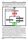
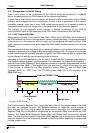
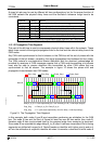
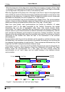
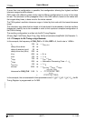
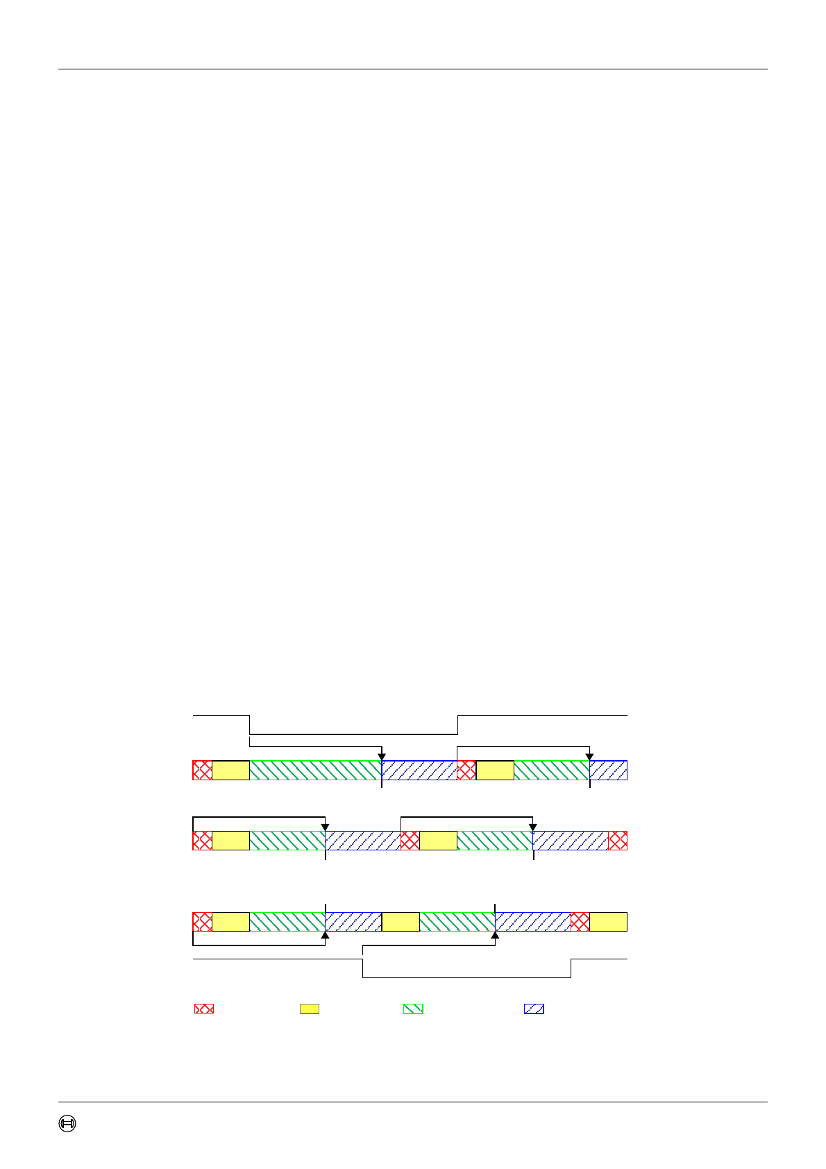
The examples in figure 11 show how the Phase Buffer Segments are used to compensate for
phase errors. There are three drawings of each two consecutive bit timings. The upper
drawing shows the synchronisation on a “
late
” edge, the lower drawing shows the
synchronisation on an “
early
” edge, and the middle drawing is the reference without
synchronisation.
Figure 11: Synchronisation on “
late
” and “
early
” Edges
recessive
dominant
recessive
dominant
Sync_Seg
Prop_Seg Phase_Seg1 Phase_Seg2
“
late
” Edge
“
early
” Edge
Rx-Input
Rx-Input
Sample-Point Sample-Point
Sample-PointSample-Point
Sample-Point Sample-Point