


User’s Manual
BOSCH
- 46/77 -
Revision 1.6TTCAN
11.11.02
manual_about.fm
A given bit rate may be met by different bit time configurations, but for the proper function of
the CAN network the physical delay times and the oscillator’s tolerance range have to be
considered.
4.2.1.2 Propagation Time Segment
This part of the bit time is used to compensate physical delay times within the network. These
delay times consist of the signal propagation time on the bus and the internal delay time of the
CAN nodes.
Any CAN node synchronised to the bit stream on the CAN bus will be out of phase with the
transmitter of that bit stream, caused by the signal propagation time between the two nodes.
The CAN protocol’s non-destructive bitwise arbitration and the dominant acknowledge bit
provided by receivers of CAN messages require that a CAN node transmitting a bit stream
must also be able to receive dominant bits transmitted by other CAN nodes that are
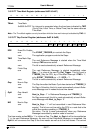
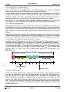
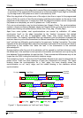
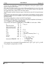
synchronised to that bit stream. The example in figure 10 shows the phase shift and
propagation times between two CAN nodes.
Figure 10: The Propagation Time Segment
In this example, both nodes A and B are transmitters performing an arbitration for the CAN
bus. The node A has sent its Start of Frame bit less than one bit time earlier than node B,
therefore node B has synchronised itself to the received edge from recessive to dominant.
Since node B has received this edge delay(A_to_B) after it has been transmitted, B’s bit timing
segments are shifted with regard to A. Node B sends an identifier with higher priority and so it
will win the arbitration at a specific identifier bit when it transmits a dominant bit while node A
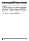
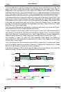
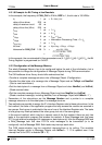
Parameter Range Remark
BRP [
1 … 32
]
defines the length of the time quantum
t
q
Sync_Seg 1
t
q
fixed length, synchronisation of bus input to system clock
Prop_Seg [1 … 8]
t
q
compensates for the physical delay times
Phase_Seg1 [1 … 8]
t
q
may be lengthened temporarily by synchronisation
Phase_Seg2 [1 … 8]
t
q
may be shortened temporarily by synchronisation
SJW [1 … 4]
t
q
may not be longer than either Phase Buffer Segment
This table describes the minimum programmable ranges required by the CAN protocol
Table 1 : Parameters of the CAN Bit Time
Sync_Seg
Prop_Seg Phase_Seg1 Phase_Seg2
Node B
Node A
Delay A_to_B Delay B_to_A
Prop_Seg >= Delay A_to_B + Delay B_to_A
Prop_Seg >= 2 • [max(node output delay+ bus line delay + node input delay)]
Delay A_to_B >= node output delay(A) + bus line delay(A→B) + node input delay(B)