


SmartSwitch ATM User Guide 8-3
ATM Filtering and Clocking Port Clock Configuration
By setting the mask appropriately, a filter could either admit or deny access to all but a few addresses within a range.
For example, if a filter’s mask is set to
00:FF:FF:FF:FF:FF:FF:FF:FF:FF:FF:FF:FF:FF:FF:FF:FF:FF:FF:FF, the
filter disregards the first byte when comparing addresses. As another example, if the filter’s mask is set to
FC:FF:FF:FF:FF:FF:FF:FF:FF:FF:FF:FF:FF:FF:FF:FF:FF:FF:FF:FF, the filter disregards the last two bits of the
first byte of the address (
FC = 11111100) when comparing addresses.
If a filter’s mask is shorter than its corresponding ATM address, the mask starts at the most significant bit, and pads
the remaining length (equal to the length of the specified ATM address) with zero bytes (00). For example, if a filter
address is specified as
39:00:00:00:00:00:00:00:00:00:14:41:80:00:20:D4:14:41:80:00, and the mask for that
address is specified as
FF:FF:FF:FF:FF:FF:FF:FF:FF:FF, the SmartSwitch ATM switch treats the mask as
FF:FF:FF:FF:FF:FF:FF:FF:FF:FF:00:00:00:00:00:00:00:00:00:00.
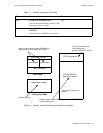
8.1.4 Filter Considerations Regarding LANE and IP over ATM
It’s important to remember that ATM address filters and filter sets cannot restrict communication between clients who
are members of the same ELAN. For example, client 1 and client 2 are members of the same ELAN. For some reason
it’s necessary to restrict client 1 from communicating with client 2. A filter is created and assigned to the port through
which client 1 connects the SmartSwitch ATM switch. The filter denies client 1 access to client 2 by rejecting the call
set up to client 2. However, once the call fails, client 1 resorts to broadcasting to client 2 through the ELAN’s BUS. In
turn, the BUS forwards the broadcast packets to client 2 and contact between client 1 and client2 is established.
ATM address filtering under LANE is more effective if the filter denies a client the ability to join an ELAN. In the
example above, client 1 could be kept from communicating with client 2 if client 1 first needed to join client 2’s ELAN.
In this case, a filter is created that denies client 1 the destination of the LANE servers. As a result client 1 cannot join
client 2’s ELAN and the two are kept from communicating.
ATM address filtering are more effective in an IP over ATM VLAN environment. Clients connect to each other by
obtaining address information form the ARP server. Once the address information is obtained, clients connect directly
to each other through the switch’s ports. Because of the client-to-client connection method of IP over ATM, filter sets
assigned to strategic ports, can effectively control (admit or deny) entities attempting to set up calls through the VLAN.
8.2 PORT CLOCK CONFIGURATION
Note The port clock features described below are supported by the SmartSwitch 6500
only.
The SmartSwitch 6500 allows the specifying source of clocking on a per-port basis. The following describes the
possible clock modes:
• Local — The port derives its clocking signal from its own oscillator
• Loopback — The port derives its clocking signal from the clock signal transmitted to it from the
device (switch, etc.) to which it’s attached
• Network — The port derives its clocking signal from a clock signal received on some port of the
switch and made available through the backplane to all ports