


3-8 SmartSwitch ATM User Guide
Multi-level PNNI Topology PNNI Routing
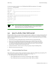
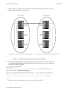
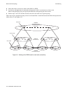
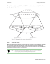
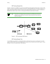
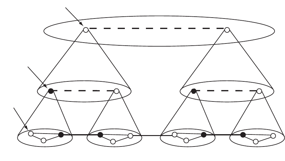
2. Add a third node (at level 64) to either switch SWA3 or SWB3.
3. Use the set pnnipglelection command to designate the switch’s second node (not third) as the
PGL for the parent peer group, and specify the third node as the parent node of the second.
4. Perform steps 2 and 3 for switches with the same role in the other level 72 parent groups.
These steps create a grandparent group at level 64, and establishes a virtual link between the LGNs that represent the
LGNs at level 72 (see Figure 3-3).
Figure 3-3 Adding a third PNNI node for next level connectivity
PGL
PGL
PGL PGL
PGL PGL
Level 80
Level 72
Level 64
First nodes
Second node
Third node
Virtual Link
Virtual Link Virtual Link
SWA3
SWA3
SWA3
SWB3
LGN LGN
Parent Groups
Grandparent Group
Lowest Peer Groups