SmartSwitch ATM User Guide 5-5
Virtual Ports and Static Connections PVP Connections
5.2 PVP CONNECTIONS
Note PVP connections are supported only on the SmartSwitch 6500. However, because
all ATM SmartSwitches support virtual ports, PVPs can be terminated using any
SmartSwitch ATM switch.
The SmartSwitch 6500 supports the creation of Permanent Virtual Path (PVP) connections. The basic process for
creating a PVP is as follows:
• Create a traffic descriptor for the PVP that meets its bandwidth and service category requirements.
• Use the set portconfig command to turn off signaling and ILMI on both ports to be connected by
the PVP.
Note Dedicated PVP switches do not signal on their physical ports. However, if desired,
you can leave signaling active on physical ports on the SmartSwitch 6500.
• Use the set portconfig command to specify a number of bits to be used for VPIs (MaxVpiBits
parameter). Note that a PVP cannot use VPI zero. Consequently, the number of VPI bits must be
greater than zero (0) on both ports. Determine the number of Available VPIs from the
MaxVpiBits
setting by using the following equation:
Available VPIs = 2
MaxVpiBits
-1
For example if
MaxVpiBits is set to 3, then Available VPIs is:
Available VPIs = 2
3
-1 = 8 -1 = 7 VPIs (VPIs 1 through 7)
We have seven Available VPIs (and not eight) because the zero (0) VPI cannot be used for PVPs.
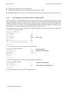
• Use the add pvp command to create the PVP connection.
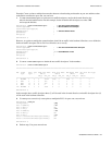
The following is a practical example of creating a PVP connection between ports
7a4 and 7b1.
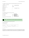
1. Use the set portconfig command to turn off signaling and ILMI and to specify bits for VPIs on
port
7a4:
SmartSwitch # set portconfig
PortNumber() : 7a4
— Specify first port for PVP
PortAdminStatus(up) :
IlmiAdminStatus(up) : down
— Turn off ILMI
SigType() : nnipvc
— Turn off signaling
SigRole(network) :
InterfaceType(private) :
MaxVpiBits(0) : 1
— 1 bit for VPIs: 2
1
-1 = 1 VPI
MaxVciBits(12) :
MaxSvcVpci(1) :
MinSvcVci(32) :
MaxVccs(8192) :
MaxSvpVpci(1) :
MaxVpcs(1) :
SmartSwitch #


