


3-4 SmartSwitch ATM User Guide
Multi-level PNNI Topology PNNI Routing
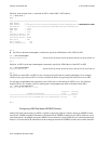
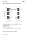
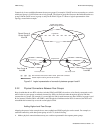
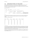
1. Physically connect switches SWA1, SWA2, and SWA3. Similarly, physically connect switches
SWB1, SWB2, and SWB3 (see Figure 3-1).
Figure 3-1 Physical connectivity for multi-peer group example
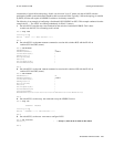
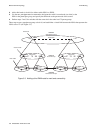
2. Use the set pnnipeergroupid command to change the peer group ID of the switches in group A to
50:39:00:00:00:00:00:00:00:00:01:00:00:00. The three remaining switches with the default peer
group ID will comprise group B:
SWA1 # set pnnipeergroupid
NodeIndex(1) :
PeerGroupId(50:39:00:00:00:00:00:00:00:00:00:00:00:00): 50:39:00:00:00:00:00:00:
00:00:01:00:00:00
— Change the tenth byte to 01
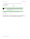
Console: You have changed the node configuration. If this node has a parent node,
make sure its parent node configuration is compatible with the new configuration.
Console: You will have to reboot for the new node configuration to take effect.
SWA1 #
Reboot the switch, and repeat the process for switches SWA2 and SWA3.
SWA1
SWA2
SWA3
SWB1
SWB2
SWB3
Peer Group A Peer Group B
Peer Group A = 50:39:00:00:00:00:00:00:00:00:01:00:00:00 Peer Group B = 50:39:00:00:00:00:00:00:00:00:00:00:00:00
Peer Group Leader Peer Group Leader