SmartSwitch ATM User Guide 3-1
3 PNNI ROUTING
All ATM SmartSwitches use PNNI version 1.0 as their default routing protocol. PNNI provides automatic and dynamic
connectivity among all PNNI nodes within the same peer group. By configuring multi-level PNNI topologies and peer
group leaders, full hierarchical PNNI routing can be established with connectivity between different peer groups.
Note For a complete explanation of all PNNI related commands, see the SmartSwitch
ATM Reference Manual.
3.1 PNNI NODE ADDRESSING
By default, all ATM SmartSwitches come configured with a single PNNI node. All PNNI nodes are in the same peer
group and at the same group level.
3.1.1 Default PNNI Addressing
All PNNI entities on SmartSwitch ATM switches are assigned default values (which can be changed). The following
describes the formulae used in creating these values.
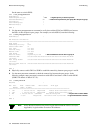
Default Peer Group ID
= 50:39:00:00:00:00:00:00:00:00:00:00:00:00
Default Group Level
= 80 (50 hexadecimal)
SmartSwitch 2500 Family Default Node ID
Default Node ID
= level + child node’s peer group level (see note) + 39 + nine zero (00) bytes + last three bytes of CPU
MAC address + CPU MAC address with 127 summed with the last byte + zero (00) byte
Note If the node does not have a child node, and the node is also at the lowest level, the
second byte is assigned the constant value A0 (160 decimal).
For example, for a node at the lowest level (80), the level and address length bytes are 50 (80 in hexadecimal) and a0
(160 in hexadecimal), respectively.
SmartSwitch 6500 Family Default Node ID
Default Node ID
= level + child node’s peer group level (see note) + 39 + nine zero (00) bytes + last three bytes of
chassis MAC address + switch MAC address with 127 summed with the last byte + zero (00) byte


