


4-10 SmartSwitch ATM User Guide
IP Routing for Management Routing
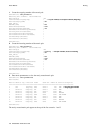
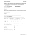
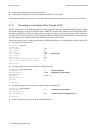
To see the route, enter the show route command on SW2
SmartSwitch # show route
ROUTE NET TABLE
destination gateway flags Refcnt Use Interface
------------------------------------------------------------------------
0.0.0.0 0.0.0.0 1 0 0 zn0
90.1.1.0 90.1.1.33 1 0 1688 zn1
128.205.99.0 90.1.1.254 1 3 5660 ei0
------------------------------------------------------------------------
ROUTE HOST TABLE
destination gateway flags Refcnt Use Interface
------------------------------------------------------------------------
127.0.0.1 127.0.0.1 5 0 0 lo0
------------------------------------------------------------------------
SmartSwitch #
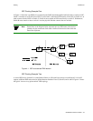
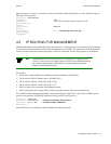
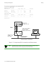
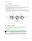
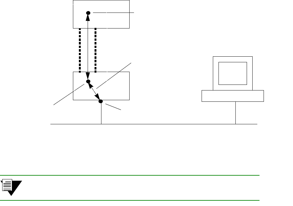
Figure 4-3 IP routing through SW1 for connectivity to the Ethernet network
Note The NMS must also contain a route that specifies the Ethernet interface of the
Ethernet connected switch as the gateway to the ELAN subnet.
NMS
Ethernet network 128.205.99.0
SW1
SW2
ATM Link
ELAN
Switch client
on SW2, 90.1.1.33
Switch client
on SW1,
IP Route
Ethernet interface
90.1.1.254
128.205.99.254
Switch client on SW1 is
defined as SW2’s
gateway to the Ethernet