


Chapter 4
4-22
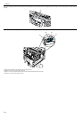
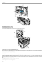
F-4-47
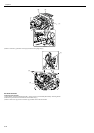
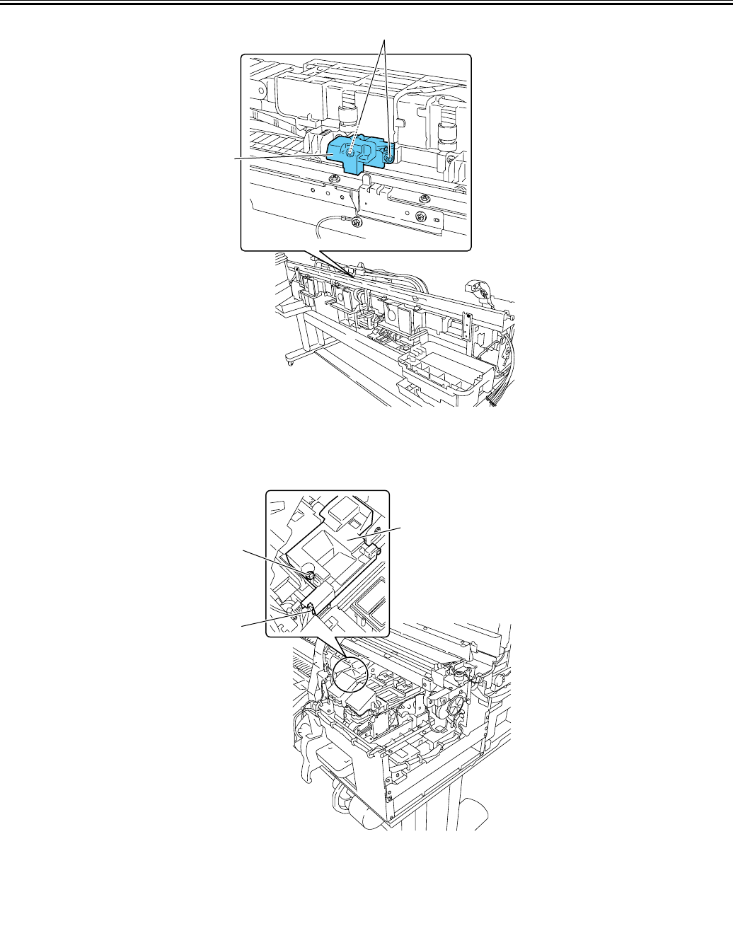
4.3.12 Head management sensor
0014-8988
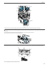
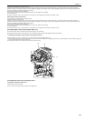
a) Removing the head management sensor
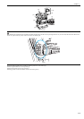
1) To remove head management sensor [1], remove screw [2] and disconnect connector [3].
F-4-48
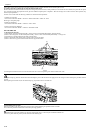
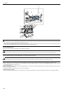
b) Action to take after replacing the head management sensor
Because the distance between the head management sensor and the carriage unit is varied from one unit to another, the printer has its optical axis corrected to adjust
the non-discharging nozzle detection position prior to shipment. When the head management sensor carriage unit has been replaced, it should require adjustment.
Execute service mode under the following conditions:
SERVICE MODE > ADJUST > NOZZLE CHK POS
4.3.13 PCBs
0014-8989
Do not replace the main controller PCB and the maintenance cartridge relay PCB (ROM board) at the same time.
Both PCBs hold vital information, such as settings and a carriage drive time. Before either PCB is replaced, such information is temporarily saved through internal
communication with the other PCB and is automatically written to the new PCB when it is installed. For this reason, the two PCBs cannot be replaced at the same
time. To replace both PCBs, work in order of (a) > (b).
When the main controller PCB and maintenance cartridge relay PCB have been replaced with service parts, check that the latest version of firmware is installed in
them.
If not, upgrade the firmware to the latest version.
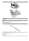
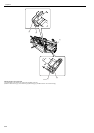
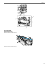
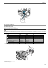
a) Replacing the maintenance cartridge relay PCB (ROM board)
1) Turn off the power and disconnect the power plug.
[1]
[2]
[2]
[3]
[1]