


Chapter 2
2-18
Even when the printer is turned off, the timer function is held on using the RTC and secondary lithium battery to assist the cleaning function.
When the power cord is plugged to the outlet, power is supplied to the RTC and therefore the secondary lithium battery power is not consumed.
Heat Enable signal control function
This function uses the pulse width to perform variable control of the time of application of the Heat Enable signal to the nozzle heater for each nozzle array (PWM
control).
Linear scale count function
This function reads the linear scale when the carriage moves, thus generating the ink jet timing. It also counts the linear scale timing cycle using the reference clock
to measure the carriage moving speed.
Dot count function
This function counts the fired dots used as the information for Heat Enable signal control, maintenance jet control, cleaning control, and remaining ink level for
each nozzle array.
Operation panel control function
This function controls serial communication with the operation panel.
PWM control function
This function controls driving of the suction fan and mist fan as well as the temperature of the printhead.
Remaining ink level detection function
This function detects the remaining level of each color of ink based on the signal received from the hollow needle mounted in the ink tank unit.
LED control function
This function controls the LEDs on the ink tank unit.
I/O port function
This function controls input signals from sensors.
Power ON/OFF control function
This function controls turning on/off of the drive power (32V and 5.1V) supplied from the power supply PCB.
Head DI sensor read control function
This function controls read operation by the head DI sensor.
Multi sensor control function
This function controls the LED, gain adjustment, and controls obtainment of the reading of the multi sensor.
EEPROM control function
This function controls the EEPROMs of individual ink tanks, the maintenance cartridge EEPROM, the EEPROM on the maintenance cartridge relay PCB, and the
head EEPROM in addition to the on-board EEPROM.
Motor control function
This function controls the carriage motor, feed motor, valve motor, purge motor, lift motor based on the input signals from sensors.
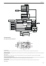
b) Driver IC (IC3100)
This IC generates a carriage motor control signal based on the control signal from the ASIC.
c) Driver IC (IC2802)
This IC generates feed motor control signal based on the control signal from the ASIC.
d) Driver IC (IC2900)
This IC generates purge motor and valve motor(R) control signals based on the control signal from the ASIC.
e) Driver IC (IC3900)
This IC generates valve motor(L) control signals based on the control signal from the ASIC.
f) Regulator IC (IC3203)
This IC generates the 3.3 V to be supplied to the tank ROM board.
g) DIMMs (IC601, IC602, IC603, IC604)
The DIMM comprising a 512-MB DDR-SDRAM and a 128-MB SDR-SDRAM is connected to the 32-bit data bus to be used as a work area.
During print data reception, it is also used as an image buffer. It cannot be expanded.
h) FLASH ROM (IC701)
A 128-MB flash ROM is connected to the 8-bit data bus to store the printer control program.
i) EEPROM (IC802)
The 128-KB EEPROM stores various setting values, adjustment values, log data, counter values related to the user/servicing.
MEMO:
After replacement of the main controller PCB, the printer must be started up in the service mode to take over the setting and adjustment values to the new PCB
properly (the service mode will be switched to the PCB replacement mode automatically).