


Chapter 2
2-1
2.1 Basic Operation Outline
2.1.1 Printer Diagram
0014-8859
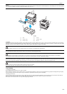
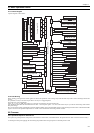
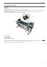
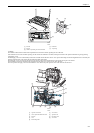
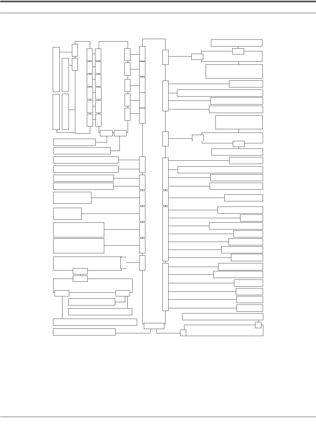
A printer diagram is shown below.
F-2-1
2.1.2 Print Driving
0012-6309
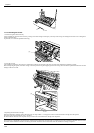
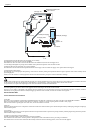
During printing, print signals and control signals are issued to the printhead via the carriage relay PCB and Head relay PCB in order to discharge ink from the
nozzles.
On a printhead, six arrays of nozzles are provided in six arrays in a staggered pattern.
This printer uses a pair of printheads.
(The Y, PC, C, PGy, Gy, MBk, PM, M, Bk, R, G, B nozzles are mounted in this order from the left.)
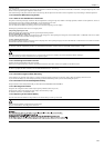
Even-numbered nozzle data and odd-numbered nozzle data -- which are print signals -- are sent to each nozzle array in sync with the data sending clock and data
latch pulse timings.
Drive control signals include a Heat Enable signal and a Sub Heat Enable signal. The Heat Enable signal is used to discharge ink from nozzles. The Sub Heat Enable
signal is used to raise the printhead temperature to a suitable value to maintain the ink discharge amount constant.
2.2 Firmware
2.2.1 Operation Sequence at Power-on
0012-6310
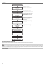
The sequence of printer operations, from power-on to transition to online mode, is flowcharted below. The printer takes less than 1 minute to initialize itself(*).
* Excluding the times spent supplying inks and cleaning the printhead after leaving the printer for extended periods of time
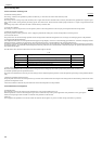
J3401
J3201J3202J3002J2501 J2502
J3602J3601J2702J3001J3150J2801J2601
J101J103J102
J701J702J703
J202J201
J101J102J103
J2701
J1801
J2
J1
J3501
J105J104
J3502
J803
J203
J802
J202
J801
J201
Ink detection sensor
Ink detection sensor
J3301
Main controller PCB
Head management sensor
Ink tank ROM PCB(L)
Humidity sensor
Carriage HP sensor
Lift motor
Pressure release switch
Purge motor
Pump encoder
Pump cam sensor
Media sensor
Feed roller encoder
Feed roller HP sensor
Suction fan
Mist fan(R)
Carriage cover sensor
Linear encoder
Upper cover lock solenoid(L)
Upper cover lock solenoid(R)
Carriage motor
Feed motor
Printhead(L)
Multi sensor
Head relay PCB
Carriage relay PCB
Maintenance cartridge relay PCB
Power supply
Operation panel
Maintenance cartridge ROM PCB
Upper cover lock switch(L)
Upper cover lock switch(R)
Mist fan(L)
Spool clutch
J2402
Valve motor(L)
Ink tank cover switch(L)
Agitation cam sensor(L)
J3003
Media take up relay PCB
J101
J102
Media take-up PCB
J102J103
Media take-up on/off sensor
Media take-up motor
Media take-up paper detection sensor
J502
Lift cam sensor
Printhead(R)
J501
Ink tank ROM PCB(R)
Valve motor(R)
Ink tank cover switch(R)
Valve open/closed detection sensor(R)
Agitation cam sensor(R)
Valve open/closed detection sensor(L)
J101
J101
J108
Ink tank
PM, M, BK, R, G, B
J108
Ink tank
Y, PC, C, PGY, GY, MBK
J101