


Chapter 2
2-20
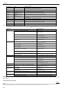
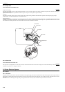
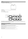
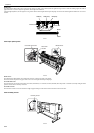
2.4.6 Maintenance Cartridge Relay PCB
2.4.6.1 Maintenance cartridge relay PCB components
0013-6532
F-2-22
a) EEPROM (IC1)
The 128-KB EEPROM stores all information written in the EEPROM on the main controller PCB.
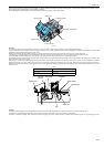
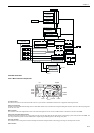
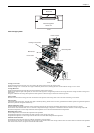
2.4.7 Power Supply
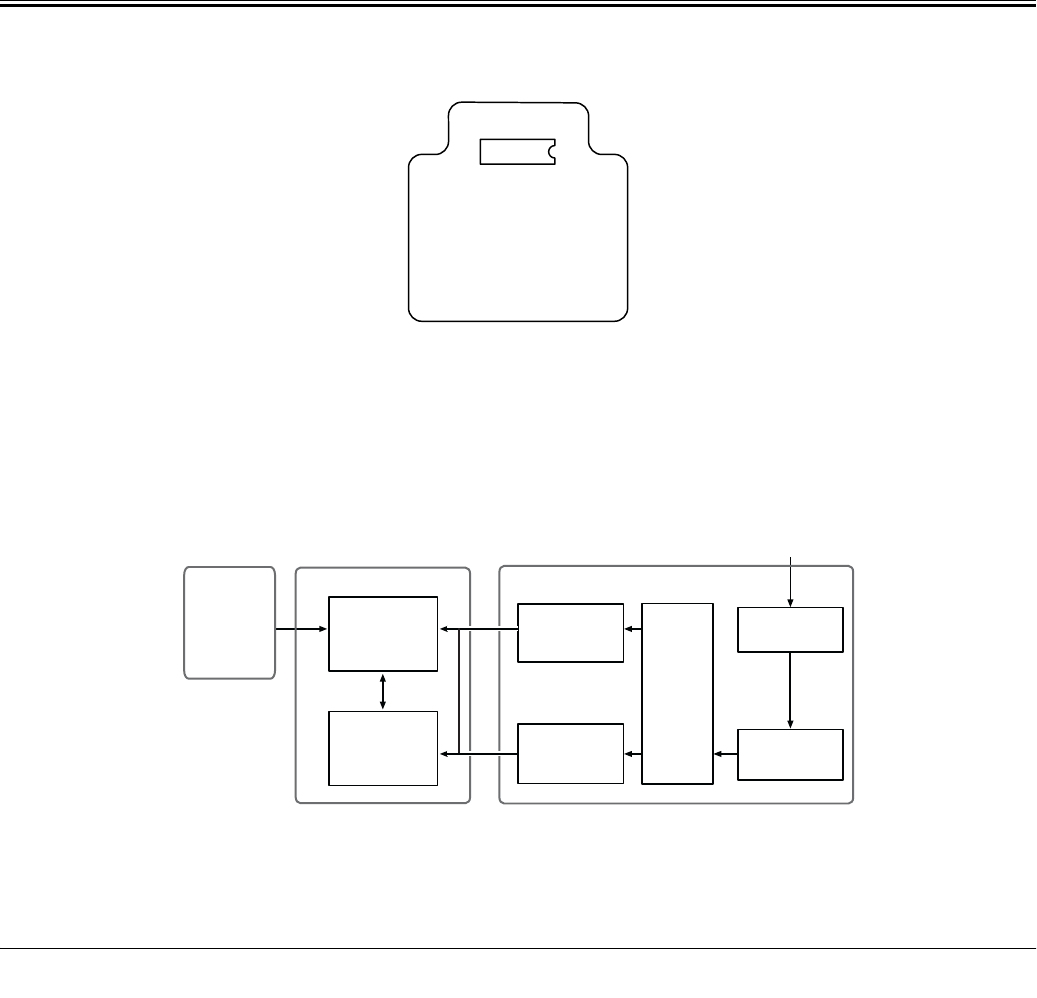
2.4.7.1 Power supply block diagram
0012-6414
F-2-23
The power supply converts AC voltages ranging from 100 V to 240 V from the AC inlet to DC voltages for driving the ICs, motor, and others.
The voltage generator circuits include the +32 V generation circuit for driving motors, fans, and the +5.1V generator circuit for driving sensors, logic circuits.
When in the power saving mode, the power supply cut outs the +32 V and the +5.1 V.
Power ON/OFF operation is controlled by the main controller PCB. When the upper cover is open, the power supply cut outs only the +32V power to the carriage.
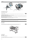
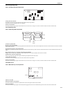
2.5 Detection Functions with Sensors
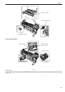
2.5.1 Cover system
0012-6490
Upper cover lock switch (L) / (R)
The microswitch-based upper cover lock switches detect the open/closed states of the upper cover.
When the upper cover close, the switches are pressed to detect the closed state of the upper cover.
The printer has one switch installed on the left and right sides each to prevent one-sided closure of the upper cover.
Ink tank cover switches (L) / (R)
The microswitch-based ink tank cover switches detect the open/closed states of ink tank covers.
When an ink tank cover closes, the switches are pressed to detect the closed state of the ink tank cover.
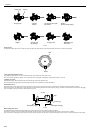
Pressure release switch
The microswitch-based pressure release switch detects the status of the paper release lever.
When the paper release lever closes, the switch is pressed to detect the closed state of the paper release lever.
IC 1
Operation panel
Transformer
DC power supply
control circuit
+5.1V
generation circuit
+32V
generation circuit
POWER ON
Rectifying circuit
Noize filter circuit
AC inlet
100V to 240V
Power supplyMain controller PCB
+5V/+3.3V
generation circuit